
Method for manufacturing surface coating of electric power insulator

A technology of surface coating and production method, applied in the field of electric power, can solve the problems of circuit failure of insulators, poor surface adhesion effect of paint and insulators, and reduced use value of insulators, etc.

Active Publication Date: 2021-06-15
醴陵市永诚电瓷电器有限公司
View PDF7 Cites 1 Cited by
  • Summary
  • Abstract
  • Description
  • Claims
  • Application Information

AI Technical Summary

Problems solved by technology

[0004] 1. In the existing coating production for the surface of power insulators, the surface of power insulators is prepared by dip coating, but for the dip coating of insulators, it is only necessary to put the insulator into the dip coating tank and pass the coating once. Take it out and place it for drying treatment. Since the paint has a certain fluidity, the existing dip coating method will make the paint attached to the surface of the insulator uneven due to the flow, resulting in poor quality of the insulator surface coating. Thereby reducing the service life of the power insulator, and may also cause circuit failure during the use of the insulator;
[0005] 2. There are two methods of coating the surface of power insulators, dipping and spraying, but neither dipping nor spraying has a process of wiping the surface of the insulator being coated, because the insulator When the surface is in a dry state, air bubbles are prone to occur when the paint adheres to the surface, resulting in poor adhesion between the paint and the insulator surface, which reduces the use value of the insulator

Method used


Image

  • Method for manufacturing surface coating of electric power insulator
  • Method for manufacturing surface coating of electric power insulator
  • Method for manufacturing surface coating of electric power insulator

Examples


Embodiment Construction

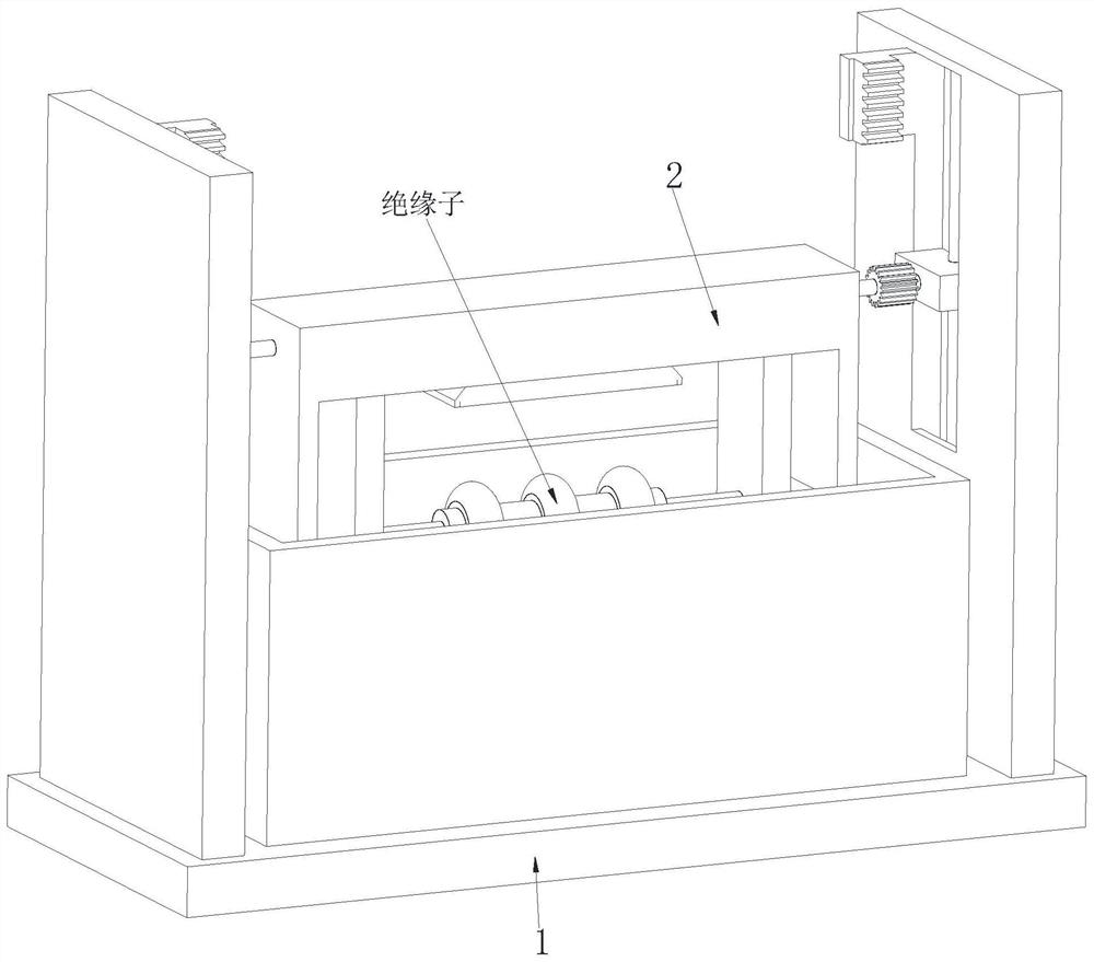
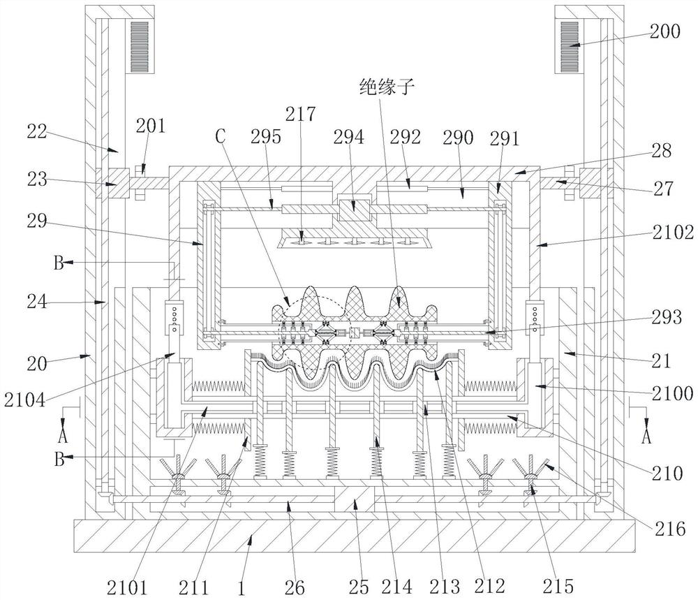
[0034] In order to make the technical means realized by the present invention, creative features, goals and effects easy to understand, the following combination Figure 1 to Figure 6 , to further elaborate the present invention.

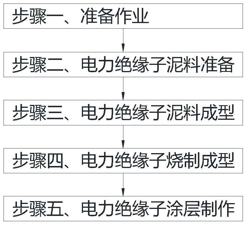
[0035] A method for manufacturing a surface coating of a power insulator, which uses a device for manufacturing a surface coating for a power insulator. The device for manufacturing a surface coating for a power insulator includes a base 1 and a coating device 2. The specific method for coating preparation on the surface of power insulators is as follows:

[0036] Step 1. Preparatory work: debugging the power insulator surface coating production equipment of the present invention;

[0037]Step 2. Power insulator mud preparation: select the appropriate mud and then crush the mud. During the crushing process, some ingredients need to be added, and then sieved to remove iron, mixed into mud and then dehydrated. mud cake, and then carry out vacuum mud...


PUM


Abstract

The invention relates to a method for manufacturing a surface coating of an electric power insulator. The method uses manufacturing equipment of the surface coating of the electric power insulator, the manufacturing equipment of the surface coating of the electric power insulator comprises a base and a coating device, and the coating device is arranged on the upper surface of the base. The problems existing when the coating is manufactured on the surface of the electric power insulator at present can be solved, specifically, the insulator is only put into a dip coating groove for coating once, then taken out, placed and dried for dip coating, the coating has certain flowability, however, according to an existing dip-coating mode, the coating attached to the surface of the insulator is not evenly attached due to the flowing reason; and the surface of the insulator is not brushed no matter in dip-coating or spray-coating, and when the surface of the insulator is in a dry state, bubbles are easily generated when the coating is attached to the surface of the insulator, so that the effect of attaching the coating to the surface of the insulator is poor.

Description

technical field [0001] The invention relates to the field of electric power, in particular to a method for manufacturing a surface coating of an electric insulator. Background technique [0002] An insulator is a device installed between conductors of different potentials or between a conductor and a component at ground potential, capable of withstanding voltage and mechanical stress. It is a special insulation control that can play an important role in overhead transmission lines, usually made of glass or ceramics, and is called an insulator. Insulators should not fail due to various electromechanical stresses caused by changes in the environment and electrical load conditions, otherwise the insulators will not play a major role. If pollution flashover occurs, it will damage the service life and operating life of the entire line. In order to solve the pollution flashover problem of insulators, coatings can be made on the surface of insulators. [0003] At present, when co...

Claims


Application Information

Patent Timeline
Patent Type & Authority Applications(China)
IPC IPC(8): H01B19/04
CPCH01B19/04Y02P40/60
Inventor 徐宾陶定红
Owner 醴陵市永诚电瓷电器有限公司
Learn More