Universal multi-level topological structure

A topology and multi-level technology, applied in the direction of electrical components, output power conversion devices, etc., can solve random and unpredictable topological problems

Inactive Publication Date: 2021-06-15
CHINA UNIV OF MINING & TECH
View PDF1 Cites 0 Cited by
  • Summary
  • Abstract
  • Description
  • Claims
  • Application Information

AI Technical Summary

Problems solved by technology

[0005] The purpose of the present invention is to provide a general-purpose multilevel topology to solve the problem that the topology formed after the topology change of the existing multilevel converter is random and unpredictable

Method used


Image

  • Universal multi-level topological structure
  • Universal multi-level topological structure
  • Universal multi-level topological structure

Examples


Embodiment 1

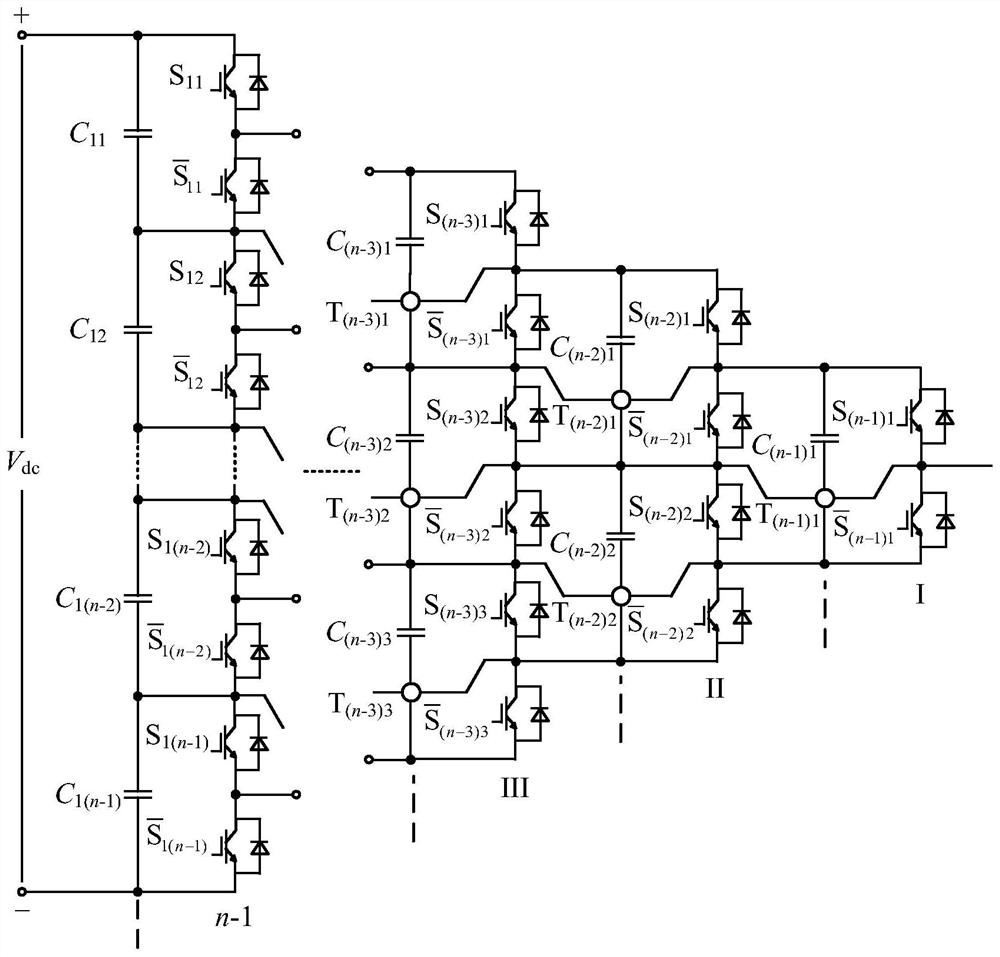
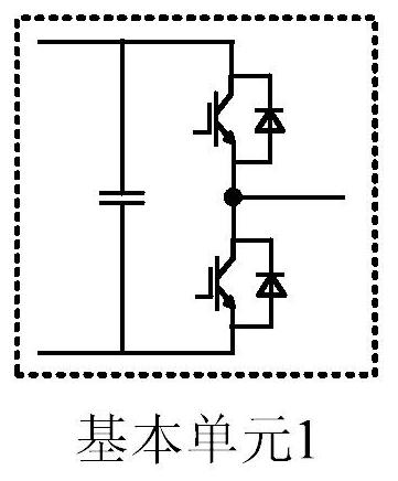
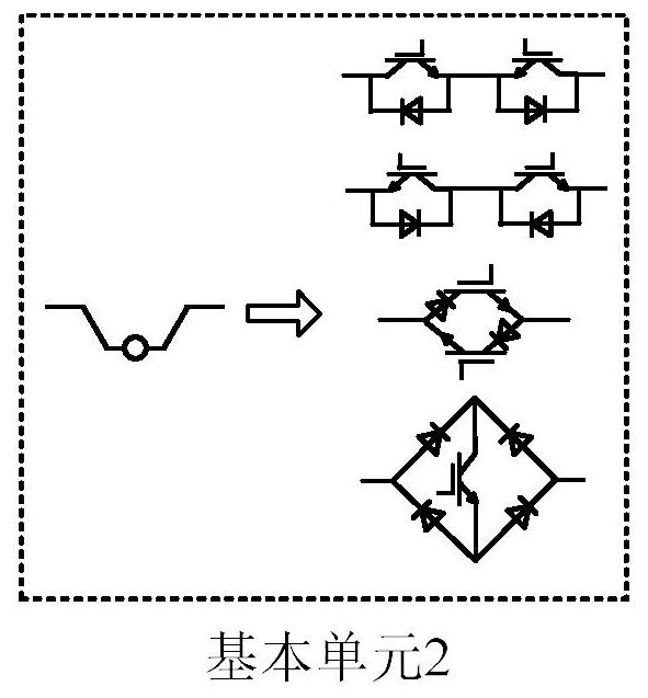
[0028] Embodiment 1: the general-purpose multilevel topology of the present invention is as figure 1 As shown, the topology is a common bus structure, and there are three bridge arm units connected in parallel with the DC bus. Each bridge arm unit has the same structure and is composed of two basic units. The number of voltage stages, an n-level general topology has n-1 circuit stages, and each circuit stage is composed of basic units. Basic unit 1 is a two-level half-bridge structure composed of two complementary insulated gate bipolar transistors and a capacitor; basic unit 2 is a path for bidirectional current flow, and there are three structures in total—two insulated gate bipolar transistors A structure composed of transistors in reverse series, two insulated gate bipolar transistors in reverse parallel, and one insulated gate bipolar transistor and four diodes.

[0029] An n-level general-purpose topology has n-1 circuit levels, and each circuit level uses one less basi...


PUM


Abstract

The invention discloses a universal multi-level topological structure, and belongs to the technical field of power electronics. The multi-level topological structure is a common-bus structure and is provided with three bridge arm units connected with a direct-current bus in parallel, and the structures of the bridge arm units are the same. Each bridge arm unit is formed by combining two basic units, the level of voltage is uniformly increased in the horizontal or vertical direction, one n-level general topological structure is provided with n-1 circuit levels, and each circuit level is formed by two basic units; the basic unit 1 is of a two-level half-bridge structure; and the basic units 2 are three combined structural forms in which current can flow bidirectionally. The universal topology can uniformly increase the level in the horizontal or vertical direction, the level number of the output voltage depends on the layer number in the structure, and an n-level topological structure has n-1 circuit stages in total. On the basis of the topological structure, various known multi-level converters can be deduced regularly, and more novel multi-level topological structures can be developed.

Description

technical field [0001] The invention relates to the technical field of power electronics, and is a general-purpose multilevel topology structure. Background technique [0002] With the rapid development of society and the emergence of new industries, people have put forward higher requirements for power electronic converters. In the low-voltage and low-power field, power electronic converters need to have the characteristics of high power density, high efficiency, and high performance; while in high-voltage and high-power industrial occasions and power transmission and distribution fields, people hope that power electronic devices can handle higher and higher Under the premise of ensuring the overall output performance of the device, it can work at a low switching frequency as much as possible to reduce electromagnetic interference and reduce switching losses. However, limited by the semiconductor manufacturing process, the traditional power electronic conversion technology...

Claims


Application Information

Patent Timeline
Patent Type & Authority Applications(China)
IPC IPC(8): H02M1/00
CPCH02M1/00
Inventor 原熙博魏琛张永磊
Owner CHINA UNIV OF MINING & TECH
Why Eureka
Try Eureka