
Driving circuit board of IPM

A technology for driving circuit boards and panels, which is applied to the circuit layout, printed circuit, and circuit device of the supporting structure, which can solve the problems of increased electrostatic influence, falling off, and easy loosening of bolts, so as to reduce development time and improve reliability. performance, ensuring stability

Active Publication Date: 2021-06-15
保定巴迪智能科技有限公司
View PDF6 Cites 1 Cited by
  • Summary
  • Abstract
  • Description
  • Claims
  • Application Information

AI Technical Summary

Problems solved by technology

[0004]The purpose of the present invention is: in order to solve the problem that when the circuit board is installed, most of them are directly fixed by using bolts, because the equipment on which the circuit board is installed usually produces Different degrees of vibration are limited by the structure of the bolt itself. The bolt is prone to loosening under the influence of vibration for a long time, and in severe cases, it will fall off, which seriously affects the stability of the environment where the circuit board operates. The impact will increase. Generally, in order to reduce the impact of static electricity, a surge suppressor is generally installed on the circuit board, which leads to the limitation of the miniaturization and integration of the circuit board, and the problem of poor destaticization effect. A drive circuit board for an IPM

Method used


Image

  • Driving circuit board of IPM
  • Driving circuit board of IPM
  • Driving circuit board of IPM

Examples


Embodiment Construction

[0043] The following will clearly and completely describe the technical solutions in the embodiments of the present invention with reference to the accompanying drawings in the embodiments of the present invention. Obviously, the described embodiments are only some, not all, embodiments of the present invention. Based on the embodiments of the present invention, all other embodiments obtained by persons of ordinary skill in the art without creative efforts fall within the protection scope of the present invention.

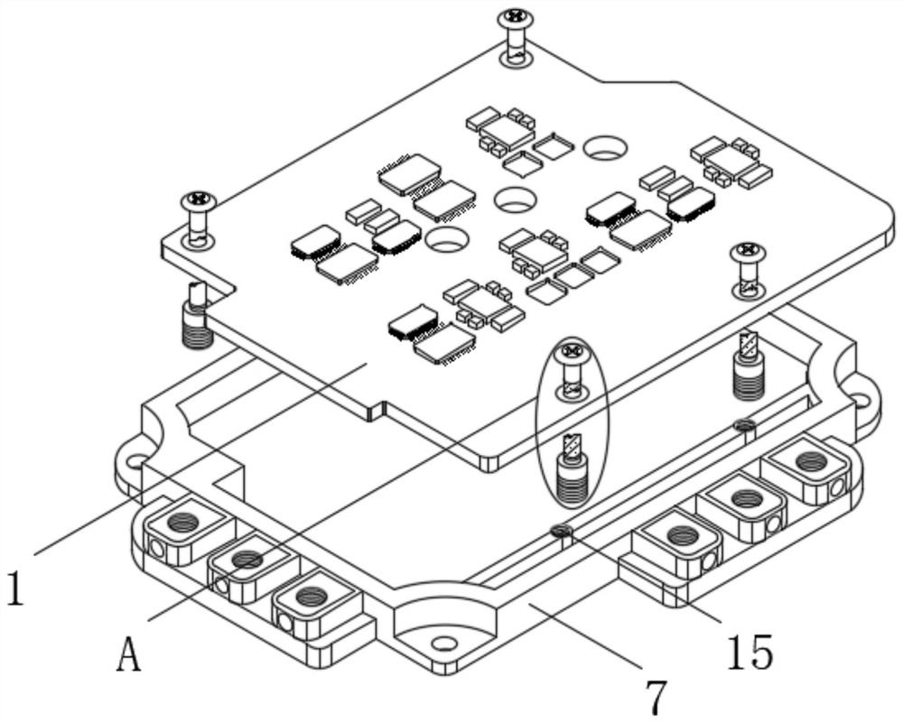
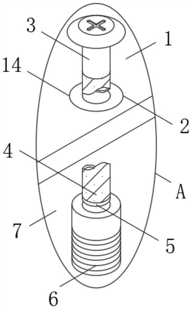
[0044] see Figure 1-6 , the present invention provides a technical solution: a drive circuit board for IPM, including a drive circuit board main body 1, through the set drive circuit board main body 1, the drive circuit board main body 1 is responsible for putting the external control signal through the signal, and controlling The IGBT is turned on and off, and the working status of the IGBT is detected at the same time. In the event of over-temperature, over-curr...


PUM


Abstract

The invention discloses a driving circuit board of an IPM, and belongs to the technical field of circuit boards. The driving circuit board comprises a driving circuit board main body, wherein a reserved mounting hole is formed in the top part of the driving circuit board main body, and an elastic connecting sleeve is clamped in the reserved mounting hole. According to the driving circuit board, under the mutual cooperation of the designed structures such as a threaded rod, a threaded panel, a first supporting spring, a limiting clamping piece, a limiting locking piece, a second supporting spring and an anti-static core plate, on the basis of preventing the threaded rod from falling off, the driving circuit board main body can be supported to a certain extent, the embedded anti-static core plate replaces a surface mounting surge suppressor, and the anti-static core plate is implanted into the driving circuit board main body, so that static protection can be performed on the driving circuit board main body from the whole system, the space can be saved, the development time can be shortened, the reliability of the driving circuit board main body in the operation process is improved, and in the field of high-density integrated electronic circuit, the driving circuit board has a relatively high application prospect.

Description

technical field [0001] The invention belongs to the technical field of circuit boards, in particular to an IPM drive circuit board. Background technique [0002] In recent years, as information, communication, and consumer electronics manufacturing have become one of the fastest growing industries in the world, high-density interconnect drive circuit boards have become an indispensable device in these electronics industries. High-density interconnect circuit boards have With fine line width and line spacing, high integration, fast operating speed, and low power, the circuit board makes the circuit more miniaturized and intuitive, and plays an important role in mass production of fixed circuits and optimizing the layout of electrical appliances. [0003] When the circuit board is installed, it is mostly directly fixed by using bolts. Since the equipment installed on the circuit board usually produces different degrees of vibration, limited by the structure of the bolt itself,...

Claims


Application Information

Patent Timeline
IPC IPC(8): H05K7/12H05K1/02H05K3/06H05K3/46
CPCH05K7/12H05K1/0259H05K3/4611H05K3/061H05K2201/0137
Inventor 张小龙李超
Owner 保定巴迪智能科技有限公司
Learn More