Tracer for navigation operation and positioning method

A positioning method and tracker technology, which is applied in the direction of surgery, surgical manipulator, surgical navigation system, etc., can solve the problems of limited movement of the robotic arm, small system tracking range, and inability to track in all directions, and achieve precise robotic arm coordinates The effect of positioning, saving medical costs, not easy to interfere or collide

Pending Publication Date: 2021-06-18
南京逸动智能科技有限责任公司
View PDF10 Cites 2 Cited by
  • Summary
  • Abstract
  • Description
  • Claims
  • Application Information

AI Technical Summary

Problems solved by technology

The disadvantage of this design is mainly that the tracking range of the system is small, usually less than ±90°, and it is not suitable for installation on a robotic arm that requires 360-degree tracking.
In addition, the existing technology is the scheme proposed by 201510547376.9, which describes the scheme of installing reflective balls on 2 to 6 surfaces. The disadvantage of this scheme is that each reflective ball is relatively large. For a small number of surfac

Method used


Image

  • Tracer for navigation operation and positioning method
  • Tracer for navigation operation and positioning method
  • Tracer for navigation operation and positioning method

Examples


Embodiment 1

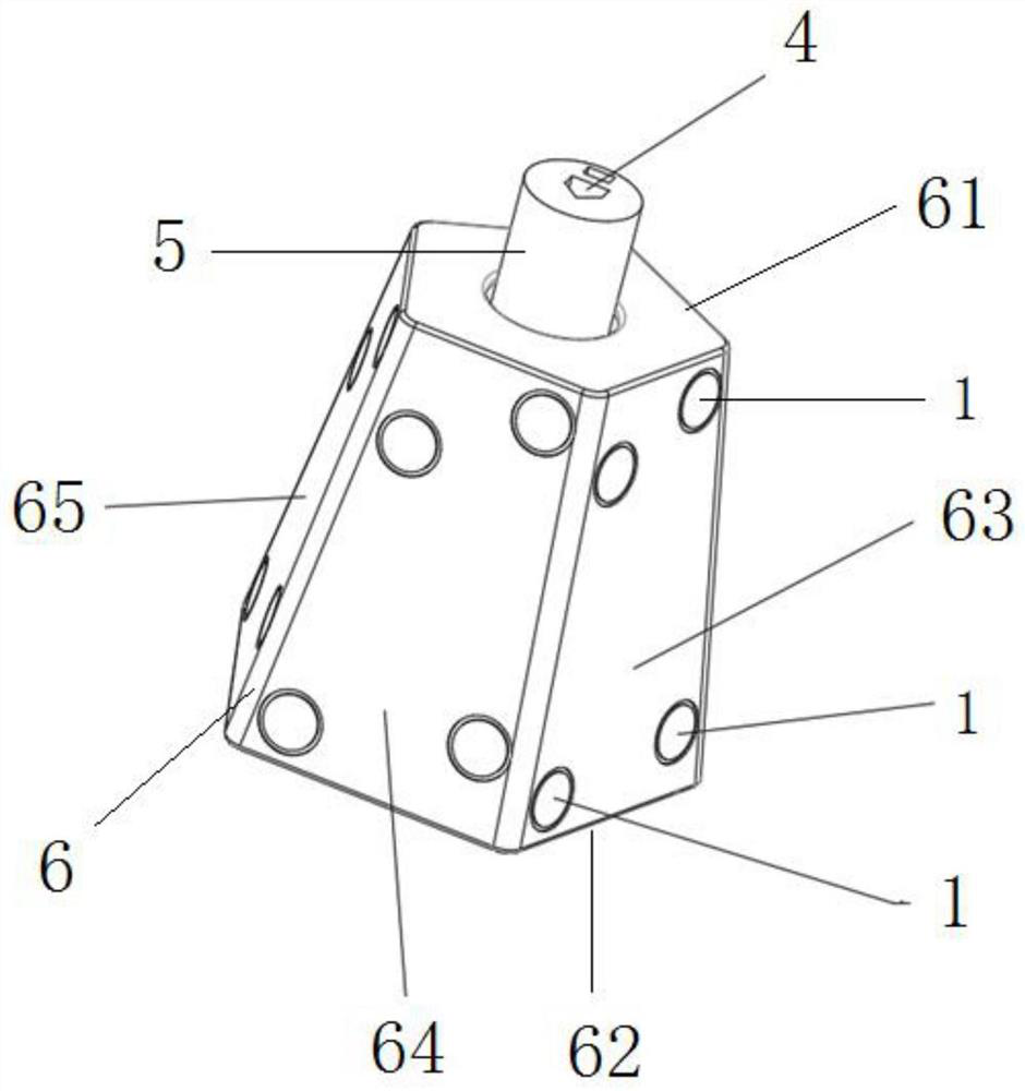
[0044] The tracker used for navigating surgery in this embodiment is installed at the end of the mechanical arm of the surgical robot, such as figure 1 As shown, it uses five trapezoidal reflective surfaces, such as figure 1 Middle trapezoidal reflective surfaces 63, 64, 65. Four circular reflective sheets 1 are pasted on each trapezoidal reflective surface, the top connection interface 4 is used to install the sleeve, and the bottom is installed on the mechanical arm. The axis 5 is set at the center of the approximately prismatic tracer body 6, the tracer body 6 consists of a pentagonal upper end face 61, a corresponding pentagonal lower end face 62, and five trapezoidal reflective surfaces all over the periphery Composition, the circumference length of described upper end surface 61 is less than the circumference length of described lower end surface 62, and each described trapezoidal surface has an inclination angle from the upper end surface to the lower end surface, and...

Embodiment 2

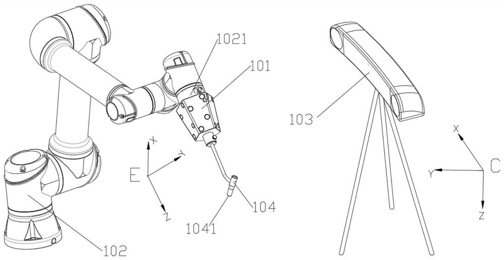
[0048] Such as figure 2 101 in the figure is the tracer used in Example 1, 102 is the robotic arm used in the navigation surgery, 103 is the optical tracker used in the navigation surgery, and 104 is indirectly fixed to the end flange 1021 of the robotic arm 102 through the tracer 101 The sleeve, where 1041 is a point on the sleeve, this example shows how to locate the point 1041.

[0049] Suppose the coordinate system of the optical tracker is C, the coordinate system at the end of the mechanical arm is E, the number of circular reflective sheets on each trapezoidal surface of the tracker 101 is 4, and each trapezoidal surface of the tracker 101 The coordinates of the center point of the circular reflective sheet 1 on the surface in the coordinate system E can be measured in advance.

[0050] The specific steps of the positioning method are:

[0051] Step 1: Fix the tracer 101 of the present invention to the flange 1021 at the end of the mechanical arm, and fix the sleeve ...


PUM


Abstract

The invention discloses a tracer for a navigation operation and a positioning method, the tracer is installed at the tail end of a mechanical arm of a surgical robot and comprises an axis and a tracing body similar to a prism, the tracing body is composed of an upper end surface with four to six edges, a lower end surface with four to six edges and four to six trapezoidal surfaces which are distributed all over the periphery, the perimeter of the upper end surface is smaller than that of the lower end surface, each trapezoidal surface has an inclination angle from the upper end surface to the lower end surface, the inclination angle ranges from 60 degrees to 90 degrees, at least three non-collinear circular reflectors are attached to each trapezoidal surface, the shape or the size of the polygon formed by the circular reflectors is different on each trapezoidal surface, so that the optical tracker can identify the current trapezoidal surface, the circular reflectors are used for reflecting infrared light emitted by the optical tracker, and the spatial position of the operating end of the mechanical arm can be determined in the surgical robot system.

Description

technical field [0001] The invention relates to a tracer for real-time tracking of the end position of a mechanical arm in a surgical robot navigation system and a positioning method thereof, belonging to the field of medical device manufacturing. Background technique [0002] In medical operations in which positioning or guidance is assisted by orthopedic surgical robots, a positioning sleeve is usually installed at the end of the robotic arm of the surgical robot. Before the operation, CT is used to determine the position of the patient's surgical site, and one or more paths are planned in the software. This path is the follow-up surgical path, such as the position and direction of the Kirschner wire or bone nail. The surgical positioning system establishes the corresponding coordinate relationship between the patient's surgical site and the position of the robotic arm through an optical tracker (also called a "navigation camera"), and then controls the movement of the rob...

Claims


Application Information

Patent Timeline
IPC IPC(8): A61B34/20A61B34/30
CPCA61B34/20A61B34/77A61B2034/2055
Inventor 周振宇罗丹
Owner 南京逸动智能科技有限责任公司
Why Eureka
Try Eureka