Precise numerical control machining equipment

A processing equipment, precision numerical control technology, applied in the direction of metal processing equipment, measuring/indicating equipment, metal processing machinery parts, etc., can solve the problems of inconvenient separation of sewage and waste, inconvenient collection of waste and sewage, difficult to achieve accurate positioning, etc., to achieve Easy to process, reduce scratch damage, and convenient to use

Inactive Publication Date: 2021-06-18
广州市景让信息科技有限公司
View PDF7 Cites 0 Cited by
  • Summary
  • Abstract
  • Description
  • Claims
  • Application Information

AI Technical Summary

Problems solved by technology

[0004] The purpose of the present invention is to provide a precision numerical control processing equipment, which solves the problem that it is not convenient to collect waste and sewage generated by processing, and it is not convenient to separate sewage and waste during the use of numerical control processing equipment on the market, and the existing The accuracy of the positioning effect of the CNC machining equipment on the clamped workpiece is low, and it is difficult to achieve precise positioning

Method used


Image

  • Precise numerical control machining equipment
  • Precise numerical control machining equipment
  • Precise numerical control machining equipment

Examples


Embodiment Construction

[0027] The following will clearly and completely describe the technical solutions in the embodiments of the present invention with reference to the accompanying drawings in the embodiments of the present invention. Obviously, the described embodiments are only some, not all, embodiments of the present invention. Based on the embodiments of the present invention, all other embodiments obtained by persons of ordinary skill in the art without making creative efforts belong to the protection scope of the present invention.

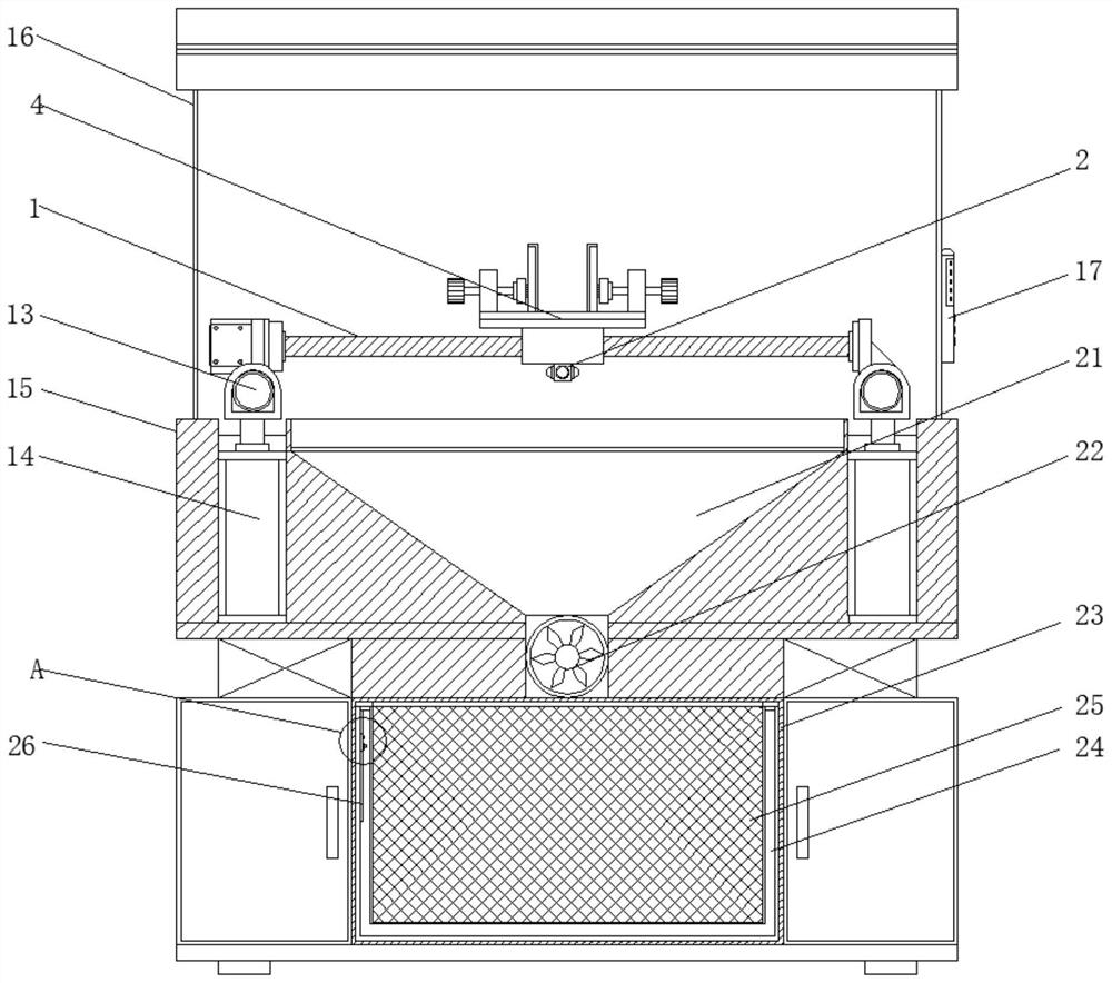
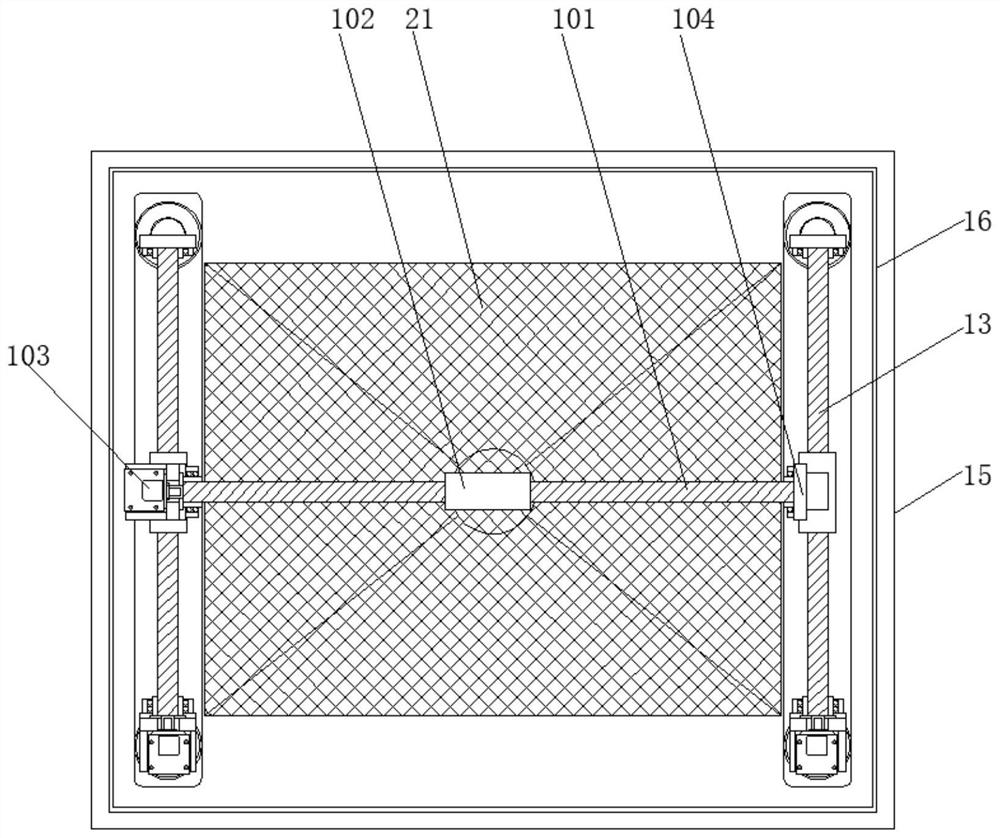
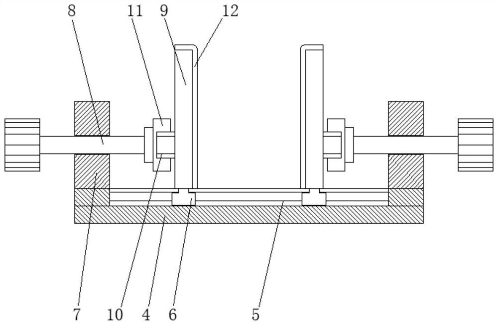
[0028] see Figure 1-6, a precision numerical control processing equipment, including an X-axis moving mechanism 1, a screw 101, a ball nut 102, a servo motor 103, a bearing seat 104, a detection block 2, a distance sensor 3, a top plate 4, a slide rail 5, and a slider 6 , support 7, screw 8, splint 9, block 10, deck 11, spacer 12, Y-axis moving mechanism 13, cylinder 14, workbench 15, enclosure 16, control panel 17, controller 18, buzzer Alarm 19, input butt...


PUM


Abstract

The invention discloses precise numerical control machining equipment. The precision numerical control machining equipment comprises an X-axis moving mechanism, clamping plates, Y-axis moving mechanisms, a control panel and a material collecting box. A detection block is installed below the middle position of the X-axis moving mechanism, distance measuring sensors are fixed to the left side, the right side, the front side and the rear side of the detection block, and the clamping plates are connected to the upper portions of sliding blocks. Clamping blocks are installed on the outer side faces of the clamping plates, the Y-axis moving mechanisms are installed below the left end and the right end of the X-axis moving mechanism correspondingly, air cylinders are connected to the lower portions of the front end and the rear end of each Y-axis moving mechanism correspondingly, the control panel is installed on the outer wall of the right side face of a surrounding plate, a controller is installed in the control panel, a material collecting box is installed below a draught fan, and a material collecting drawer is arranged in the material collecting box. According to the precise numerical control machining equipment, the Y-axis moving mechanisms and the X-axis moving mechanism are arranged to be perpendicular to each other, then a plane coordinate axis is formed, a machined part can be accurately positioned conveniently, the adjusting precision is effectively improved, and the burden of workers can be relieved.

Description

technical field [0001] The invention relates to the technical field of mechanical processing equipment, in particular to precision numerical control processing equipment. Background technique [0002] CNC machining refers to a process method for processing parts on CNC machine tools. The process regulations of CNC machine tool processing and traditional machine tool processing are generally consistent, but significant changes have also taken place. A machining method that uses digital information to control the movement of parts and tools. It is an effective way to solve the problems of variable varieties of parts, small batches, complex shapes, and high precision requirements, and to achieve high-efficiency and automatic processing. CNC machining has the following advantages: greatly reducing the number of tooling, and machining parts with complex shapes does not require complicated tooling. If you want to change the shape and size of the part, you only need to modify the...

Claims


Application Information

Patent Timeline
Patent Type & Authority Applications(China)
IPC IPC(8): B23Q1/25B23Q17/22B23Q3/06B23Q11/00
CPCB23Q1/25B23Q3/06B23Q11/00B23Q11/0042B23Q17/22
Inventor 陈觉
Owner 广州市景让信息科技有限公司
Why Eureka
Try Eureka