A Feedforward Compensation Control System and Method for Improving the Passive Leveling System of a Hydraulic Press

A feed-forward compensation and control system technology, applied in presses, manufacturing tools, etc., can solve the problems of reducing the pressure of the lower cavity of the leveling cylinder, affecting the leveling effect, and high energy consumption of the main cylinder, so as to reduce the pressure of the lower cavity, Guaranteed tightness and the effect of meeting energy-saving needs

Active Publication Date: 2021-11-30
FUZHOU UNIV
View PDF0 Cites 0 Cited by
  • Summary
  • Abstract
  • Description
  • Claims
  • Application Information

AI Technical Summary

Problems solved by technology

[0005] The existing technology helps to solve the problem of lagging response of the control valve at the moment of docking between the movable beam and the leveling cylinder and the high energy consumption of the main cylinder during the no-load leveling stage, but there are still some shortcomings and limitations, mainly as follows:
[0006] (1) The commonly used valve signal compensation method is to give a fixed compensation value, but its value cannot be accurately predicted. It can only be debugged through experience to match the valve signal compensation value with the actual speed of the movable beam
That is, it is easy to cause the following effects: although the small valve compensation can keep the movable beam and the leveling cylinder in close contact after docking, it cannot optimally reduce the pressure in the lower chamber of the leveling cylinder, and the excessive valve compensation will easily cause the movable beam and the leveling cylinder to be in close contact. Each leveling cylinder is separated, so that each leveling cylinder in the leveling system loses the leveling control of the movable beam
[0007] (2) The valve compensation value calculated based on the target speed of the movable beam cannot be optimized, and after the mold on the movable beam is pressed to the billet, the compensation value cannot effectively match the actual speed of the movable beam
That is to say, the compensation value can be predicted by the target speed of the movable beam and the valve port flow formula, but it is very easy for the predicted compensation value to be too large, so that the spool opening of the leveling control valve is relatively large, and the leveling cylinder descends quickly , resulting in insufficient tightness of the contact between the movable beam and the leveling cylinder
Especially after the movable beam is pressed to the load, the actual speed of the movable beam cannot continue to accurately track its target speed due to the sudden increase of the load force on the movable beam, resulting in the compensation value no longer matching the actual speed of the movable beam, resulting in cylinder separation
[0008] (3) The existing valve signal compensation value is only applicable to the no-load leveling stage before the movable beam and the upper mold are pressed to the load, and in the loaded leveling stage, if the load is not at the center of the movable beam, it will cause a surge in the movable beam The eccentric load moment of the original valve signal causes the initial leveling torque of the leveling system to be insufficient, which cannot effectively balance the eccentric load moment at this stage, which affects the leveling effect
At this time, the leveling control valve generates leveling torque by controlling the pressure in the lower cavity of each leveling cylinder to achieve leveling of the movable beam. The pressure in the lower chamber cannot be rapidly increased to form a large leveling torque, and the surge of unbalanced load torque cannot be balanced, resulting in poor steady-state leveling accuracy

Method used


Image

  • A Feedforward Compensation Control System and Method for Improving the Passive Leveling System of a Hydraulic Press
  • A Feedforward Compensation Control System and Method for Improving the Passive Leveling System of a Hydraulic Press
  • A Feedforward Compensation Control System and Method for Improving the Passive Leveling System of a Hydraulic Press

Examples


Embodiment Construction

[0035] The present invention will be further described below in conjunction with the accompanying drawings and embodiments.

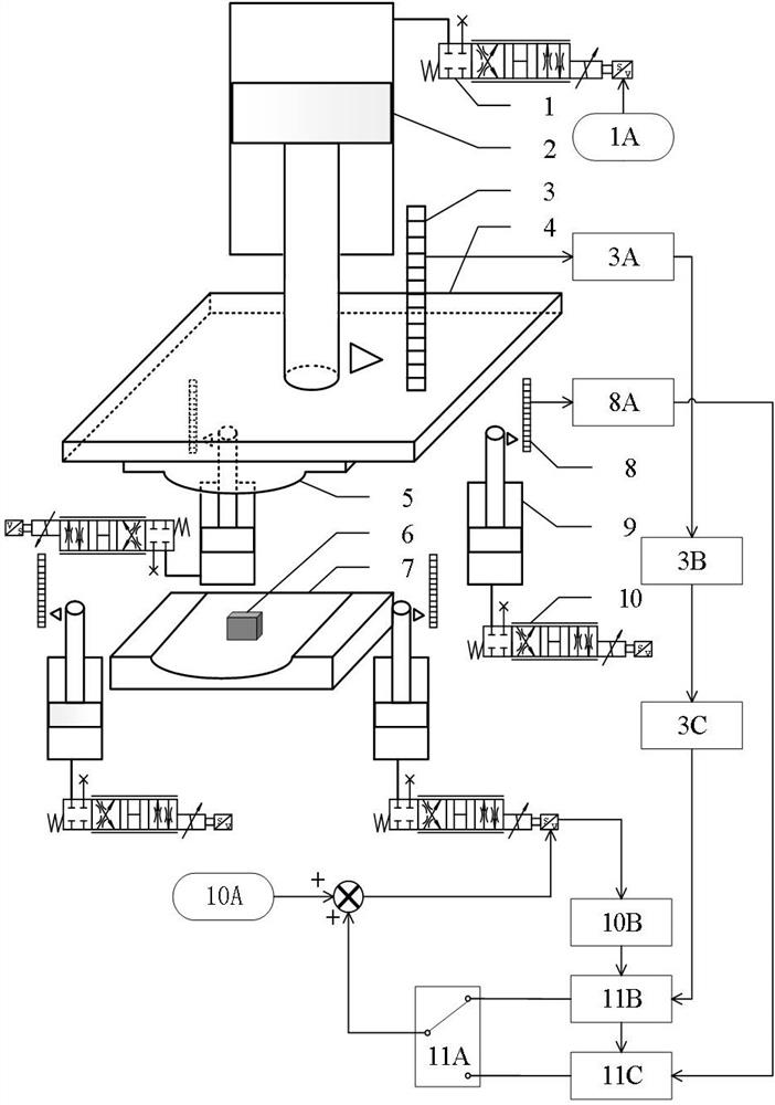
[0036] figure 1 Schematically represents the working principle of the present invention.

[0037] In this embodiment, the system composition of the hydraulic press includes a master cylinder drive system and a passive multi-hydraulic cylinder leveling system, wherein the direct drive objects of the master cylinder drive system are the movable beam 4 and the upper mold 5, the actuator is the master cylinder 2, The displacement variation of the master cylinder piston is the displacement variation of the movable beam and the upper mold. In the stage of multi-cylinder leveling, by giving the master cylinder control valve 1 a movable beam position control signal 1A, the feedback displacement 3A of the movable beam monitored by the displacement sensor is controlled according to the target displacement for closed-loop position control. The actuators of the ...


PUM


Abstract

The invention relates to a feed-forward compensation control system and method for improving the passive leveling system of a hydraulic machine. In the no-load leveling stage, the actual speed of the movable beam is calculated and output through the Kalman filter through the first valve compensation signal operation module. Through the change of the feedback signal of the spool of the leveling control valve in the previous pressing cycle, the parameter optimization of the compensation calculation of the current cycle valve is realized, and then the optimal flow rate at the outlet of the lower chamber of the leveling cylinder and the variable speed movement of the movable beam are realized. Optimal matching, while reducing the pressure in the lower chamber of the leveling cylinder, further reducing the energy consumption of the master cylinder. In the pre-load leveling stage, the valve compensation value calculated by the second valve compensation calculation module for the former decays to a smaller value through the optimal transition curve with a variable slope with slow attenuation in the front stage and fast attenuation in the rear stage, so as to realize the control of the master cylinder pressure and The smooth transition of the pressure of the leveling cylinder increases, which makes the position tracking of the master cylinder and the steady state accuracy of the leveling in the subsequent load leveling stage better.

Description

technical field [0001] The invention relates to the field of hydraulic control systems, in particular to a feedforward compensation control system and method for improving the passive leveling system of a hydraulic machine. Background technique [0002] Hydraulic press refers to a mechanical device that uses high-pressure liquid to transmit working pressure. The common mechanical structure is three beams (upper beam, lower beam and movable beam) and four columns (four columns). It is one of the most widely used large-scale equipment in industrial production. The upper mold is installed on the lower plane of the movable beam, and the movable beam and the upper mold are driven by the pressure of the main cylinder to complete the mold clamping with the lower mold to realize the pressing of the material. The horizontality of the lower surface of the movable beam determines the pressing performance of the hydraulic press and the precision of the finished material. The early hydra...

Claims


Application Information

Patent Timeline
Patent Type & Authority Patents(China)
IPC IPC(8): B30B15/16B30B15/26B30B15/00
CPCB30B15/00B30B15/166B30B15/26
Inventor 杜恒刘闽张泽鑫汪启港黄惠李雨铮
Owner FUZHOU UNIV
Why Eureka
Try Eureka