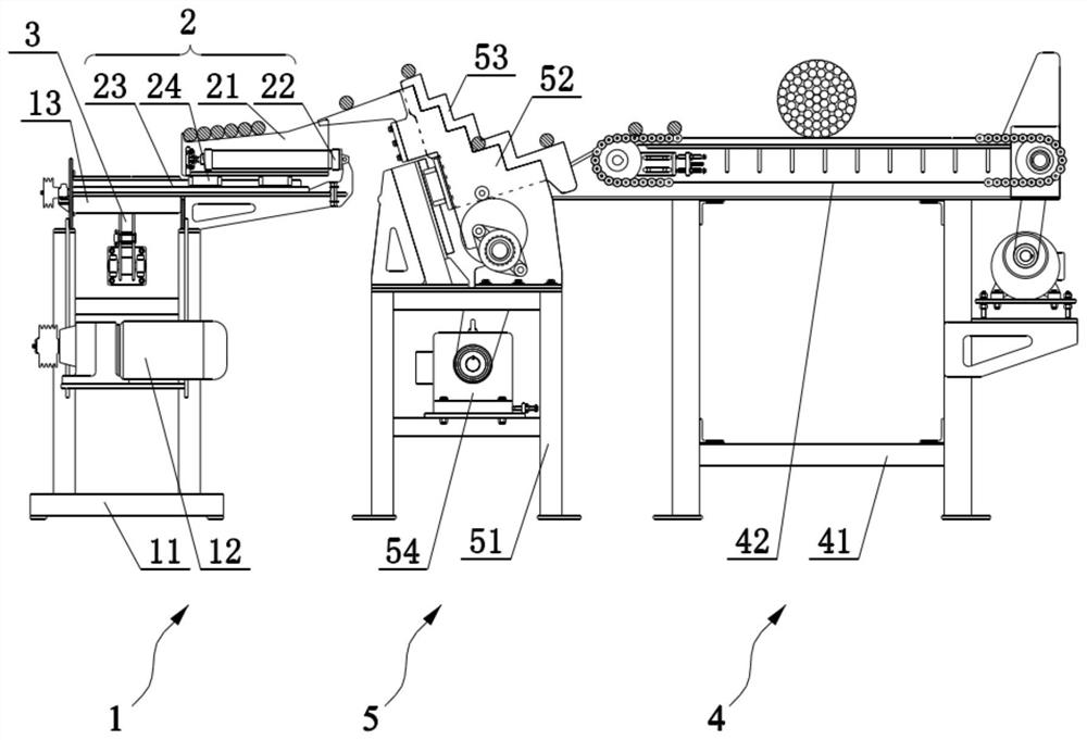
Steel bar feeding system
A technology for steel bar and material moving, which is applied to conveyor objects, transportation and packaging, roller tables, etc., can solve the problems of labor and time-consuming, damage to steel bars to be cut, and labor intensity of workers, so as to achieve safe and reliable operation and reduce labor. Strength, the effect of improving production efficiency
- Summary
- Abstract
- Description
- Claims
- Application Information
AI Technical Summary
Problems solved by technology
Method used
Image

Examples
Embodiment Construction
[0044] Embodiments of the present invention will be described in detail below, and examples of the embodiments are shown in the drawings, wherein the same or similar reference numerals denote the same or similar components or components having the same or similar functions throughout. The embodiments described below by referring to the figures are exemplary and are intended to explain the present invention and should not be construed as limiting the present invention.
[0045] In the description of the present invention, unless otherwise clearly stipulated and limited, the terms "connected", "connected" and "fixed" should be understood in a broad sense, for example, it can be a fixed connection, a detachable connection, or a mechanical connection. A connection can also be an electrical connection, a direct connection, or an indirect connection through an intermediary, or an internal connection between two elements or an interaction relationship between two elements. Those of o...
PUM
 Abstract
Description
Claims
Application Information
 - R&D
- Intellectual Property
- Life Sciences
- Materials
- Tech Scout
- Unparalleled Data Quality
- Higher Quality Content
- 60% Fewer Hallucinations
Browse by: Latest US Patents, China's latest patents, Technical Efficacy Thesaurus, Application Domain, Technology Topic, Popular Technical Reports.
© 2025 PatSnap. All rights reserved.Legal|Privacy policy|Modern Slavery Act Transparency Statement|Sitemap|About US| Contact US: help@patsnap.com