Supercharge Your Innovation With Domain-Expert AI Agents!

Corrugated steel underground chamber structure

A technology for underground chambers and corrugated steel, applied in underground chambers, shaft linings, tunnel linings, etc., can solve problems such as slow construction progress, poor mechanical performance, complex structure of underground chambers, etc., to speed up construction progress, The effect of fast construction speed and shortened construction period

Pending Publication Date: 2021-06-18
XIAN CENTURY METAL STRUCTURE CO LTD
View PDF0 Cites 2 Cited by
  • Summary
  • Abstract
  • Description
  • Claims
  • Application Information

AI Technical Summary

Problems solved by technology

[0004] The purpose of the present invention is to provide a corrugated steel underground chamber structure, which mainly solves the problems of complex underground chamber structure, slow construction progress and poor mechanical performance in the prior art

Method used


Image

  • Corrugated steel underground chamber structure
  • Corrugated steel underground chamber structure
  • Corrugated steel underground chamber structure

Examples


Embodiment 1

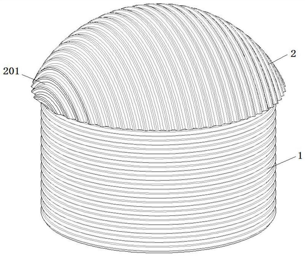
[0029] see figure 1 , a corrugated steel underground chamber structure, comprising a steel corrugated plate dome structure and a composite concrete support structure arranged outside the steel corrugated plate dome structure, the steel corrugated plate dome structure includes a tank body 1 and a ball arranged on the upper end of the tank body 1 The crown 2 and the tank body 1 are sequentially stacked and welded or bolted to form a barrel-shaped structure by multiple sets of ring-shaped steel corrugated plates. The lower end of the tank body 1 is provided with connectors, which are bolted or welded to the embedded parts of the inner cap of the surrounding rock (not shown in the figure). The corrugated plate 3 is spliced, and the lower end of the spherical cap 2 is bolted or welded to the upper end of the tank body 1;

[0030] see Figure 5 , the composite concrete support structure includes anchorage system 4 and concrete system 5, anchorage system 4 includes the anchor cable...

Embodiment 2

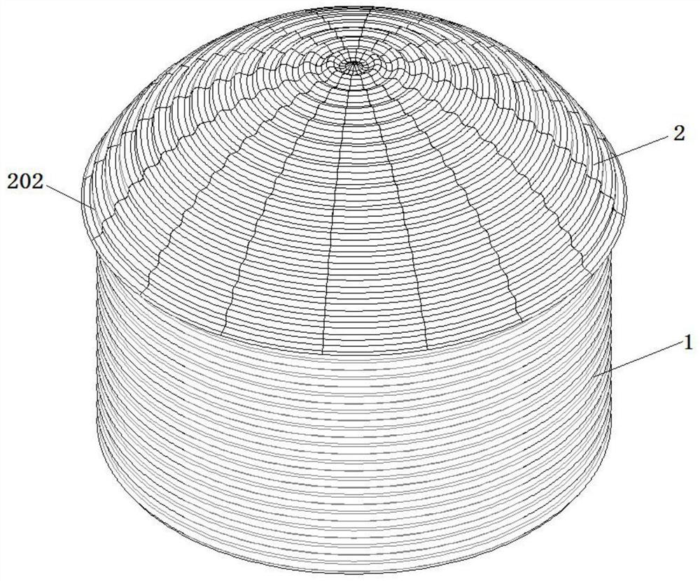
[0033] see figure 2 , different from Embodiment 1, in this embodiment, the spherical cap 2 is sequentially bolted or welded horizontally through multiple fan-shaped corrugated steel strips 202 to form an arched cover, and the fan-shaped corrugated steel strips 202 are made of several steel corrugated plates 3. Bolted or welded horizontally or vertically in turn.

Embodiment 3

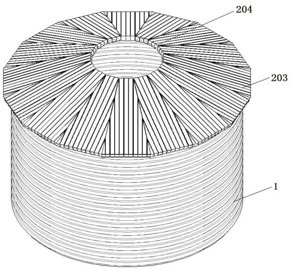
[0035] see image 3 , different from Embodiment 1, the spherical crown 2 includes an outer ring crown 203, a center frame 204 and an inner crown (not shown in the figure), and the center frame 204 is a regular hexagonal hollow frame structure, and the hollow frame is filled with In self-compacting concrete, each side of the center frame 204 is bolted or welded with a piece of fan ring corrugated steel belt 202, and multiple fan ring corrugated steel belts 202 are sequentially bolted or welded to form an outer ring crown 203, and the fan ring corrugated steel belt 202 is composed of A number of corrugated steel plates 3 of different lengths are bolted or welded in turn horizontally or vertically. The inner crown is welded on the upper part of the center frame, and the inner crown is an arched small cover formed by connecting several steel corrugated plates.

[0036] In this embodiment, the central frame 204 is a regular hexagonal hollow frame structure. In other embodiments, th...


PUM


Abstract

The invention provides a corrugated steel underground chamber structure. The corrugated steel underground chamber structure comprises a steel corrugated plate dome structure and a composite concrete supporting structure arranged outside the steel corrugated plate dome structure; the steel corrugated plate dome structure comprises a tank body and a spherical crown arranged at the upper end of the tank body; the tank body is in a barrel shape formed by sequentially connecting a plurality of sets of annular steel corrugated plates in an overlapped mode; the lower end of the tank body is fixedly connected with an embedded part in a bearing platform; the spherical crown is of an arch-shaped cover body structure and is formed by splicing the multiple sets of steel corrugated plates; the composite concrete supporting structure comprises an anchoring system and a concrete system; the steel corrugated plate dome structure and underground surrounding rock are fixed through the anchoring system; and the space between the steel corrugated plate dome structure and the underground surrounding rock is filled with the concrete system. According to the corrugated steel underground chamber structure, a multi-point supporting thin-shell spherical crown stress system is formed through the steel corrugated plates, the steel corrugated plate structure of the system can serve as a stress formwork function of secondary lining while providing supporting, the construction progress is greatly accelerated, the construction period is effectively shortened, and the stress performance is improved.

Description

technical field [0001] The invention belongs to the technical field of underground chambers, and in particular relates to a corrugated steel underground chamber structure. Background technique [0002] There are many types of chambers, which can be roughly divided into mechanical chambers and production service chambers. Mechanical chambers mainly include ore unloading chambers, crusher chambers, loading chambers, etc.; production service chambers include waiting room chambers, medical room chambers, explosive storage chambers, etc. Due to the different purposes of various underground chambers, their shapes, specifications and structures vary greatly, and the properties of the rocks they pass through are also different, so there are many structures. [0003] The structure of the chamber in the prior art is complicated, the installation and construction are inconvenient and the progress is slow, and the mechanical performance is not good. SUMMARY OF THE INVENTION [0004]...

Claims


Application Information

Patent Timeline
Patent Type & Authority Applications(China)
IPC IPC(8): E21D13/00E21D11/15E21D11/10E21D21/00
CPCE21D11/102E21D11/105E21D11/155E21D13/00E21D21/00
Inventor 赵建华王志杰王兴平郭春唐慧枝鲁醒周鲁楠
Owner XIAN CENTURY METAL STRUCTURE CO LTD
Features
  • R&D
  • Intellectual Property
  • Life Sciences
  • Materials
  • Tech Scout
  • Unparalleled Data Quality
  • Higher Quality Content
  • 60% Fewer Hallucinations
Learn More