
Heat recovery device of heating ventilation air conditioning system

A technology of HVAC system and heat recovery device, which is applied in the direction of air conditioning system, ventilation system, ventilation and heating energy recovery system, etc. It can solve the problems of affecting heat recovery efficiency, loose cleaning filter belt, and reduced air circulation of the device. , to achieve the effect of saving capital consumption, convenient operation and increasing inhalation volume

Active Publication Date: 2021-06-18
广东国祥环境科技有限公司
View PDF7 Cites 0 Cited by
  • Summary
  • Abstract
  • Description
  • Claims
  • Application Information

AI Technical Summary

Problems solved by technology

[0005] In order to solve the above technical problems, the present invention provides a heat recovery device for HVAC systems to solve the problem that during the use of the existing heat recovery devices for HVAC systems, when the fresh air duct sucks in fresh air from the outside, due to the large amount of suction, it will A large amount of resource consumption will be generated, and at the same time, the mist will gather on the front water shield, and the deposited water droplets will easily block the ventilation holes of the front water shield, resulting in reduced air circulation in the device, affecting the heat recovery efficiency, and the cleaning filter belt will be affected by moisture. Or the influence of hot air to loosen the situation, resulting in the problem that the cleaning filter belt filtering effect is greatly reduced

Method used


Image

  • Heat recovery device of heating ventilation air conditioning system
  • Heat recovery device of heating ventilation air conditioning system
  • Heat recovery device of heating ventilation air conditioning system

Examples


Embodiment

[0036] as attached figure 1 to attach Figure 9 Shown:

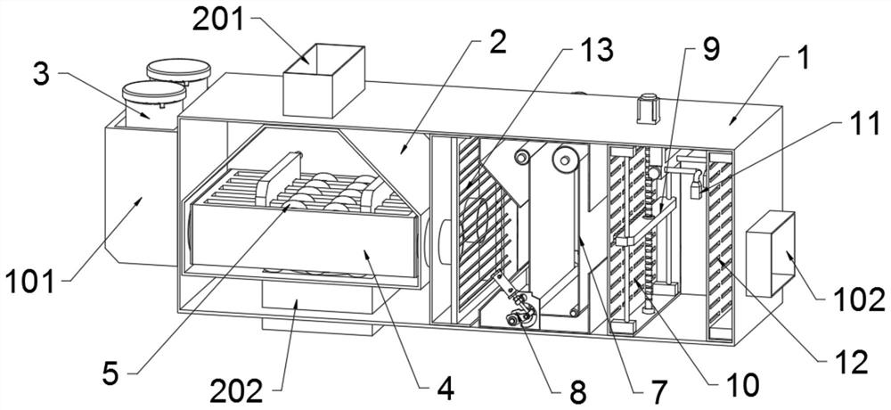
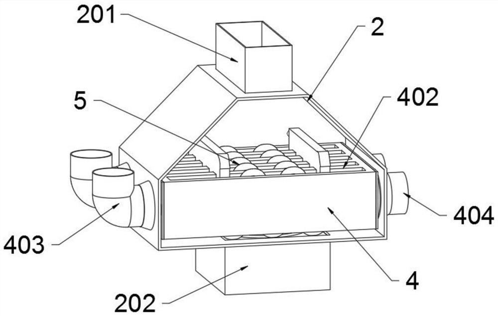
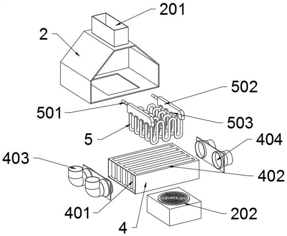
[0037] The present invention provides a heat recovery device for an HVAC system, comprising a casing 1, the casing 1 includes a sleeve frame 101 and an air supply pipe 102, the casing 1 is a rectangular cavity structure, and the rear end of the casing 1 is provided with an air supply pipe 102, and the front end of the casing 1 A sleeve frame 101 is provided, and two fresh air pipes 3 are arranged inside the sleeve frame 101, and a first motor 6 is arranged inside the sleeve frame 101, and the first motor 6 is arranged between the two fresh air pipes 3; 3 includes a cover 301, a dustproof plate 302 and a booster plug 303. The two fresh air ducts 3 are all cylindrical through-cavity structures, and the top of the fresh air duct 3 is provided with a cover 301, and the top of the fresh air duct 3 is provided with a cavity top. There is a dustproof plate 302, and a booster plug 303 is provided in the cavity of the fresh air...


PUM


Abstract

The invention provides a heat recovery device of a heating ventilation air conditioning system, and relates to the technical field of air conditioning system equipment. The heat recovery device aims to solve the problems that in the using process of an existing heat recovery device of the heating ventilation air conditioning system, when a fresh air pipe sucks external fresh air, a large amount of resources are consumed due to the large suction amount, and meanwhile mist is gathered on a front water baffle, due to the fact that deposited water drops are prone to blocking vent holes of the front water baffle, air circulation in a device is reduced, heat recovery efficiency is affected, and the filtering effect of a cleaning filter material belt is greatly reduced due to the fact that the cleaning filter material belt is affected by moisture or hot air to be loosened. The heat recovery device comprises a shell, the shell comprises a sleeve frame and an air supply pipe, and an air supply pipe is arranged at the rear end of the shell. According to the heat recovery device, power is provided by a first motor, a shaft rod and a rotating plate continuously rotate, a transmission rod drives a pressurizing plug to reciprocate up and down in a fresh air penetrating pipe, and therefore the pressurizing effect is achieved, the suction amount of fresh air is increased, energy consumption is reduced, and capital consumption is reduced.

Description

technical field [0001] The invention belongs to the technical field of air-conditioning system equipment, and more specifically relates to a heat recovery device for an HVAC system. Background technique [0002] The air conditioning system is a system that uses artificial methods to deal with the temperature, humidity, cleanliness and airflow velocity of the indoor air, so that certain places can obtain air with a certain temperature, humidity and air quality to meet the requirements and needs of users and production processes. Improving labor hygiene and indoor climate conditions, on the basis of variable air volume control, optimizing the temperature and humidity of supply air and realizing optimal control of surface coolers, heaters and humidifiers is an important method to further reduce energy consumption of air conditioning systems; The supply air temperature is also an important energy-saving adjustment method commonly used in constant air volume air conditioning syst...

Claims


Application Information

Patent Timeline
IPC IPC(8): F24F1/0063F24F1/0087F24F12/00F24F13/20F24F13/24F24F13/28F24F13/30
CPCF24F12/006F24F1/0063F24F1/0087F24F13/24F24F13/30F24F13/20F24F13/28
Inventor 叶滨
Owner 广东国祥环境科技有限公司
Learn More