Piston type wind tunnel special gas inflation method utilizing compressed air power

A technology of special gas and compressed air, which is applied in the field of wind tunnel test, can solve the problems of low inflation efficiency, slow inflation speed, and small safety risk, and achieve the effect of high inflation efficiency, fast inflation speed and high safety

Active Publication Date: 2021-06-18
中国空气动力研究与发展中心超高速空气动力研究所
View PDF28 Cites 3 Cited by
  • Summary
  • Abstract
  • Description
  • Claims
  • Application Information

AI Technical Summary

Problems solved by technology

[0006] There are generally two ways to replace the removable large-capacity gas storage tank to replenish special gas to the fixed gas storage tank. One is direct pipeline transmission without power. The advantage of this method is that it does not require a booster or a compressor. The simplest method; the disadvantage is also obvious, the inflation efficiency of special gas is low. For the removable large-capacity gas storage tank whose volume is equivalent to that of the fixed gas storage tank, when about half of the special gas is filled, the mobile large-capacity overall replacement The gas storage tank and the fixed gas storage tank reach a pressure balance, and the remaining special gas cannot be recharged. The final pressure of the fixed gas storage tank is only about half of the initial pressure of the removable large-capacity overall replacement gas storage tank, and the inflation efficiency is about 50%. , when the fixed air storage tank has residual air, the inflation efficiency is lower
The other is powered compressor inflation, which uses a compressor to boost the inflation between the movable large-capacity overall replacement gas storage tank and the fixed gas storage tank. This method is easy to operate and has low safety risks; the disadvantage is that it needs to be configured separately Compressors, large compressors are expensive, take up a lot of space, and require a lot of auxiliary configurations such as power distribution systems, cooling systems, etc. Small compressors have limited compression ratios, more residual gas in the air tank, and low efficiency of special gas inflation. slower

Method used


Image

  • Piston type wind tunnel special gas inflation method utilizing compressed air power
  • Piston type wind tunnel special gas inflation method utilizing compressed air power

Examples


Embodiment 1

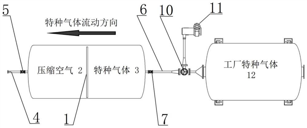
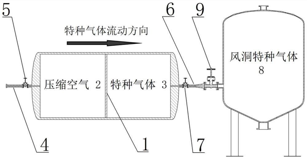
[0053] The volume of the fixed gas storage tank 8 of the present embodiment is 10m3, and the volume of the piston type gas storage tank is 8m 3 , the pressure is 15MPa, and the weight is 4.7 tons. Using the 16MPa wind tunnel high-pressure gas source, the CF4 gas in the piston gas storage tank is filled to the fixed gas storage tank 8 within 10 minutes. The pressure of the fixed gas storage tank 8 is 12MPa. Under the jet flow rate of 5 kg per second, a total of 31 wind tunnel jet tests can be completed in a single 30-second period, which can meet the needs of the first-phase wind tunnel jet test.


PUM


Abstract

The invention discloses a piston type wind tunnel special gas inflation method utilizing compressed air power. A device used in the inflation method comprises a piston type gas storage tank, and a sliding piston in the middle of the piston type gas storage tank divides the piston type gas storage tank into an air cavity and a special gas cavity. During inflation, the special gas cavity is connected with a fixed gas storage tank of the wind tunnel, the air cavity is connected with a high-pressure gas source of the wind tunnel, stop valves of the air cavity and the special gas cavity are opened, air of the high-pressure gas source always keeps high pressure, the piston slowly presses all the special gas into the fixed gas storage tank, and the stop valves of the special gas cavity are closed after inflation is completed. The stop valve of the air cavity is opened, the high-pressure air in the air cavity is emptied, the high-pressure air cannot generate any pollution gas, and the inflation efficiency of the special gas is close to 100%. The inflation method is simple, efficient, low in cost and low in noise, inflation of a large amount of special gas can be rapidly completed, and smooth proceeding of a wind tunnel jet flow test is effectively guaranteed.

Description

technical field [0001] The invention belongs to the technical field of wind tunnel tests, and in particular relates to a method for inflating special gas in a piston type wind tunnel using compressed air power. Background technique [0002] In recent years, the wind tunnel has been equipped with a special gas jet simulation system. Generally, in the jet flow test, special gases such as CF4 and SF6 with low specific heat ratio that are easy to condense, or H2 with high specific heat ratio that are not easy to condense are used, or special gas mixtures are used. The production of special gases requires the support of the chemical industry. The price of special gases is much higher than that of air, and the amount of special gases used by jet flow is far less than that used by wind tunnel flow. Therefore, the wind tunnel site is usually not equipped with special gas manufacturing equipment, and does not have the qualification to process and manufacture special gas. It is neces...

Claims


Application Information

Patent Timeline
Patent Type & Authority Applications(China)
IPC IPC(8): G01M9/04G01M9/02
CPCG01M9/04G01M9/02
Inventor 解福田侯峰伟舒海峰陈久芬林敬周许晓斌孙启志赖小平王南天
Owner 中国空气动力研究与发展中心超高速空气动力研究所
Why Eureka
Try Eureka