
Monitoring terminal of laboratory ultrasonic biological treatment device

A monitoring terminal and biological processing technology, applied in biological testing, measuring ultrasonic/sonic/infrasonic waves, measuring devices, etc., can solve the problem of fine frequency adjustment of different objects, which consumes manpower, financial resources, and material resources, and cannot guarantee high efficiency. Frequency and other issues, to achieve the effect of reducing the space occupied by the machine body, improving the utilization rate, and intuitive and clear operation

Active Publication Date: 2021-06-18
BEIBU GULF UNIV
View PDF5 Cites 0 Cited by
  • Summary
  • Abstract
  • Description
  • Claims
  • Application Information

AI Technical Summary

Problems solved by technology

In essence, such a method cannot guarantee that the working ultrasonic frequency is the optimal frequency for the object, nor can it perform precise and fine frequency adjustments for different objects, and the accumulated experience is not the best process; in addition, the The method not only consumes a lot of manpower, financial resources and material resources in the initial stage, but also often requires observation, adjustment and maintenance during the use period.

Method used


Image

  • Monitoring terminal of laboratory ultrasonic biological treatment device
  • Monitoring terminal of laboratory ultrasonic biological treatment device
  • Monitoring terminal of laboratory ultrasonic biological treatment device

Examples


Embodiment Construction

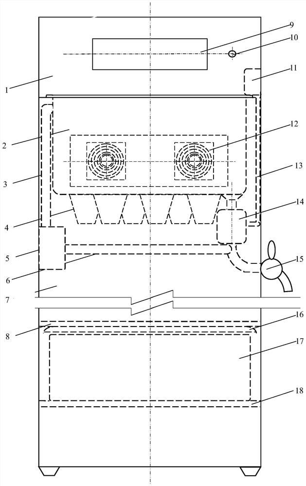
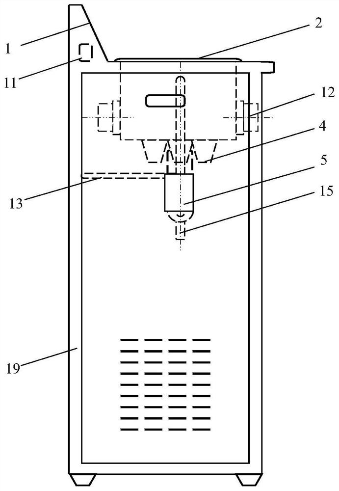
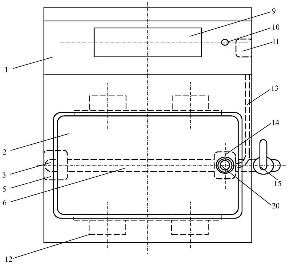
[0035] exist figure 1 In the front view of the device structure shown in the present invention: the operating surface 1 is a mechanism part for man-machine interaction support and operation, which is a rectangular structure of stainless steel sheet material, pasted on the top rear side of the body 7, facing forward. The treatment tank 2 is a body component for containing the treatment liquid of the target object, and is a rectangular parallelepiped tank structure made of 304 stainless steel, and is assembled on the upper end of the body 7 . The return pipe 3, as a processing liquid circulation and homogeneous body running component, is a 304-type stainless steel circular tube structure, and is assembled in the cavity between the left wall of the casing on the left side of the body 7 and the left wall of the treatment tank 2. The transducer 4 is used as an element for converting the electric energy of the ultrasonic frequency into mechanical energy of the same frequency, and is...


PUM


Abstract

A monitoring terminal of a laboratory ultrasonic biological treatment device consists of a shielding shell, a temperature measuring part, a sound transmission tube, a connecting hoop, a light transmitting tube, a light projecting part, a light measuring part, a sound measuring part, a lower coupling, an upper coupling and a short section, and the temperature sensing surface of the temperature measuring part is attached to the left surface of the sound transmission tube. The tube wall of the sound transmission tube is made of a 304 type stainless steel sound guide material thin plate, the upper port of the sound transmission tube is connected and communicated with a front guide pipe of a monitoring terminal through the upper coupling, and the lower port is connected and communicated with the light-transmitting tube through a connecting hoop. The tube wall of the light transmitting tube is made of a high-temperature glass full-transparent material, the upper port of the light transmitting tube is connected and communicated with the sound transmission tube through a connecting hoop, and the lower port is connected and communicated with a rear conduit of the monitoring terminal through the lower coupling. The LED light projection end face of the light projecting part is attached to the left face of the light transmitting tube. The light measuring part is a set of 200-400 nM ultraviolet sensitive device circuit components, and the light receiving end faces of the light measuring part are attached to the right face of the light transmitting tube. And the sound receiving surface of the sound measuring part is attached to the right surface of the sound transmission tube.

Description

technical field [0001] The invention relates to a laboratory ultrasonic biological treatment device, process and method. Background technique [0002] The laboratory equipment, process and method of ultrasonic biological treatment are still in the mode of single-frequency treatment, group control and inductive effect. The current laboratory method of ultrasonic biological treatment is: by setting or selecting a certain working frequency of the ultrasonic generating equipment in advance, and then using the ultrasonic frequency of this frequency to act on the treatment object. However, the processing rate of ultrasonic waves on objects is highly correlated with ultrasonic frequency, and the processing efficiency varies greatly with different ultrasonic frequencies; moreover, the type of biological cells to be processed is highly related to ultrasonic frequency, and different biological cells are sensitive to different frequency ultrasonic waves. very different. This has caus...

Claims


Application Information

Patent Timeline
IPC IPC(8): G01N33/48G01N21/33G01K7/20G01H17/00
CPCG01H17/00G01K7/20G01N21/33G01N33/48
Inventor 屈百达程宪宝姜愉梁家海胡俐蕊农国才
Owner BEIBU GULF UNIV
Learn More