Eureka AIR delivers breakthrough ideas for toughest innovation challenges, trusted by R&D personnel around the world.

Method and equipment for testing measurement error of satellite navigation receiver under dynamic condition

A satellite navigation and measurement error technology, which is applied in the direction of measuring devices, radio wave measurement systems, satellite radio beacon positioning systems, etc., can solve the problems of difficult to accurately determine the reference position, difficult to fix the ambiguity, difficult to measure the receiver measurement error, etc. problem, to achieve the effect of reducing the number of unknowns, improving the success rate and accuracy, and reducing the size of the hardware device

Active Publication Date: 2021-06-18
NAT UNIV OF DEFENSE TECH
View PDF10 Cites 7 Cited by
  • Summary
  • Abstract
  • Description
  • Claims
  • Application Information

AI Technical Summary

Problems solved by technology

Such a measurement result may not be equivalent to the measurement error of the receiver in the dynamic environment commonly used by users
However, it is more difficult to correctly fix the ambiguity under dynamic conditions, and the reference position is also difficult to be given accurately, which makes it more difficult to measure the receiver measurement error

Method used


Image

  • Method and equipment for testing measurement error of satellite navigation receiver under dynamic condition
  • Method and equipment for testing measurement error of satellite navigation receiver under dynamic condition
  • Method and equipment for testing measurement error of satellite navigation receiver under dynamic condition

Examples


Embodiment Construction

[0055] In order to make the purpose, technical solution and advantages of the present application clearer, the present application will be further described in detail below in conjunction with the accompanying drawings and embodiments. It should be understood that the specific embodiments described here are only used to explain the present application, and are not intended to limit the present application.

[0056] The test method for satellite navigation receiver measurement error provided by this application under dynamic conditions can be applied to such as figure 1 Shown is a test device for satellite navigation receiver measurement errors under dynamic conditions. The device includes: a dual-frequency satellite navigation receiver 101 (such as figure 1 shown in a), as a static reference station; a rigid turntable (such as figure 1 As shown in b), the rotating shaft 103 of the turntable can rotate around a single axis, and the speed is controllable. When , the rotation ...


PUM


Abstract

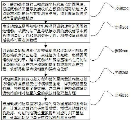
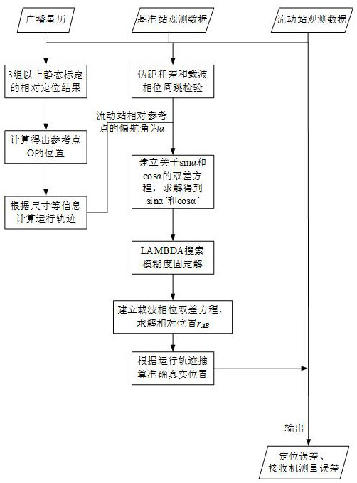
The invention relates to a method, equipment and system for testing a measurement error of a satellite navigation receiver under a dynamic condition, computer equipment and a storage medium. The method comprises the following steps of: establishing an inter-station inter-satellite pseudo-range double-difference equation and a carrier phase double-difference equation of a static base station and a receiver to be tested by using the static base station and the receiver to be tested moving along a known circular track and taking sine and cosine values of inter-station inter-satellite double-difference ambiguity and a yaw angle of the receiver to be tested relative to the circle center of the track as unknown numbers; carrying out solving and ambiguity fixing, establishing an inter-station inter-satellite carrier phase double-difference equation of a relative position vector from the base station to the receiver to be measured, calculating the accurate position of the receiver to be measured according to an effective fixed solution and a known circular track, and obtaining the measurement error of the receiver to be tested by combining broadcast ephemeris. The receiver measurement error under the dynamic condition can be tested, the test under the complex environment can be conveniently carried out, the ambiguity floating point solution solving success rate and accuracy are improved, and the error measurement result is more comprehensive and reliable.

Description

technical field [0001] The application relates to the field of antenna measurement error testing in satellite navigation and positioning, in particular to a method and equipment for testing measurement errors of satellite navigation receivers under dynamic conditions. Background technique [0002] The measurement error of satellite navigation signal receiver under dynamic conditions is one of the important evaluation contents of receiver performance. Under non-fault conditions, the carrier phase measurement error can be divided into cycle slip and normal measurement error. When using carrier phase for high-precision positioning, if the cycle slip is not eliminated or repaired, it will usually cause at least a decimeter-level positioning error. Therefore, the cycle The occurrence probability and distribution characteristics of jumps and the characteristics of normal measurement errors will directly limit the usage scenarios of the equipment and affect the usability of the equ...

Claims


Application Information

Patent Timeline
Patent Type & Authority Applications(China)
IPC IPC(8): G01S19/23
CPCG01S19/23
Inventor 熊晨耀吴杰宋远李青松王鼎杰
Owner NAT UNIV OF DEFENSE TECH
Why Eureka
Eureka Blog
Learn More