
A method for measuring the ignition time of electric ignition head

A technology of ignition time and measurement method, which is applied in the direction of electrical unknown time interval measurement, devices for measuring time interval, clocks and watches, etc., can solve the problems of poor measurement accuracy, long ignition time, inaccuracy, etc., and achieve high and accurate time measurement accuracy High accuracy and precision, simple system installation

Active Publication Date: 2022-03-11
深圳市珈玛纳米技术有限公司
View PDF9 Cites 0 Cited by
  • Summary
  • Abstract
  • Description
  • Claims
  • Application Information

AI Technical Summary

Problems solved by technology

[0003] (1) Ignition current on-off method: the main disadvantage is that under the condition of rated ignition current, the bridge wire may not be fused, resulting in inaccurate measurement of ignition time
Since the ignition time is measured by the method of measuring the on-off of the current, the measurement accuracy is poor. It is based on the starting time of adding the ignition current and the termination time of the ignition current circuit disconnection. It is obtained by calculating the time difference between the two ignition time
The source of the measurement error is that the ignition current is delayed when the ignition current is applied to the pyrotechnic product of the electric igniter, and the second is that when the bridge wire of the pyrotechnic product of the electric igniter is burned out, the ignition process has already been completed, so the measured ignition time is longer than the actual one. still long time
[0004] (2) Target line method: the main disadvantage is that the target line is bound and cumbersome, and the target line may burn continuously, resulting in inaccurate measurement
However, there will be shortcomings such as low reliability of the test due to insufficient binding of the target wires and failure to burn the target wires.
[0005] (3) Acoustic emission method: The main problem is that the speed of sound propagation is slow, and the time measurement accuracy of microsecond level cannot be achieved
[0006] (4) High-speed camera method: the main problem is that the measurement system is expensive and needs to be equipped with an X-ray light source

Method used


Image

  • A method for measuring the ignition time of electric ignition head
  • A method for measuring the ignition time of electric ignition head
  • A method for measuring the ignition time of electric ignition head

Examples


Embodiment Construction

[0026] The idea, specific structure and technical effects of the present invention will be further described below in conjunction with the accompanying drawings, so as to fully understand the purpose, features and effects of the present invention.

[0027] It should be noted that, in the description of the present invention, terms such as "up", "down", "left", "right", "vertical", "horizontal", "inside", "outside" and so on indicate directions or The terms of positional relationship are based on the direction or positional relationship shown in the drawings, which are only for convenience of description, and do not indicate or imply that the device or element must have a specific orientation, be constructed and operated in a specific orientation, and therefore cannot be understood To limit the present invention.

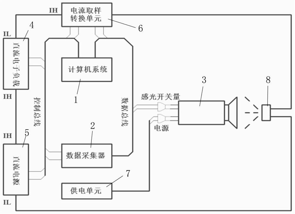
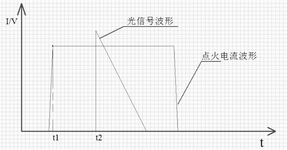
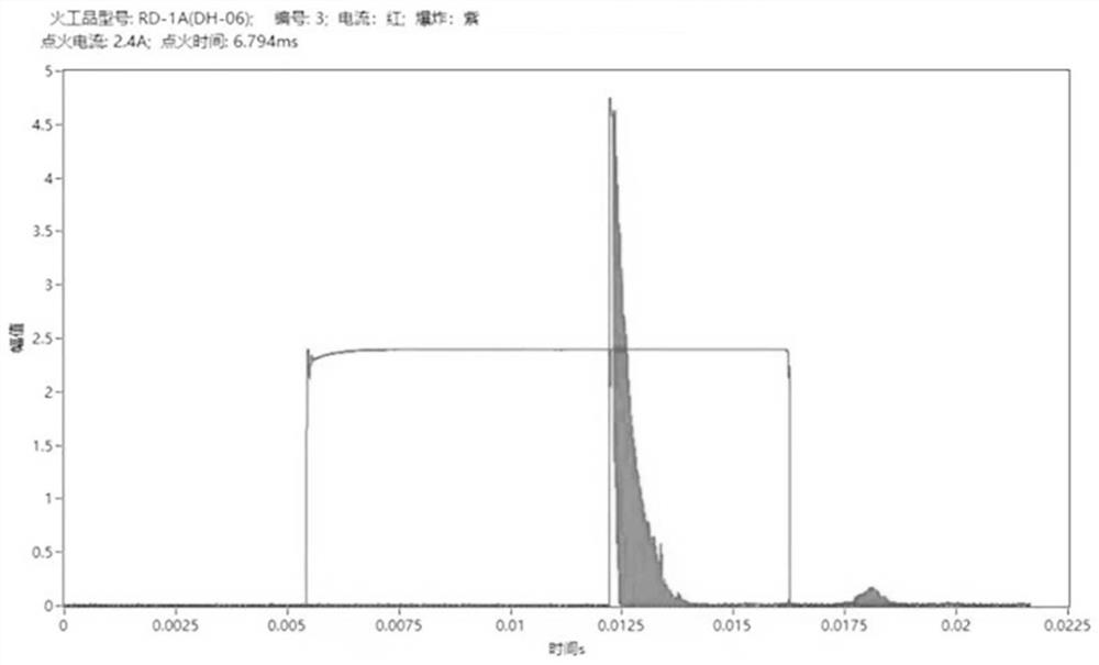
[0028] refer to figure 1 , 2 Shown in , 3 is a schematic diagram of a preferred embodiment of the present invention. The present invention relates to a method for ...


PUM


Abstract

The invention relates to a method for measuring the ignition time of an electro-generating head. The method provides a computer detection system for testing, adopts differential measurement, utilizes the visible light generated when the pyrotechnic product of the electro-generating head is ignited, and picks up the visible light signal through a high-speed photoelectric sensor. Then, through the computer system, the visible light signal is compared with the ignition current signal added to the pyrotechnic product, and the time difference between the two signals is calculated to obtain an accurate ignition time of the pyrotechnic product. The invention has high accuracy and precision in measuring ignition time, is convenient to operate, and is safe and reliable. System installation is simple and inexpensive.

Description

technical field [0001] The invention relates to the technical field of photoelectric detection, in particular to a method for measuring the ignition time of an electric ignition head. Background technique [0002] The measurement of the ignition time of the traditional electric igniter pyrotechnics mainly adopts the following methods: [0003] (1) Ignition current on-off method: The main disadvantage is that under the condition of rated ignition current, the bridge wire may not be fused, resulting in inaccurate measurement of ignition time. Since the ignition time is measured by the method of measuring the on-off of the current, the measurement accuracy is poor. It is based on the starting time of adding the ignition current and the termination time of the ignition current circuit disconnection. It is obtained by calculating the time difference between the two ignition time. The source of the measurement error is that the ignition current is delayed when the ignition curre...

Claims


Application Information

Patent Timeline
Patent Type & Authority Patents(China)
IPC IPC(8): G04F10/00
CPCG04F10/00
Inventor 田亮张子林
Owner 深圳市珈玛纳米技术有限公司
Learn More