Unlock instant, AI-driven research and patent intelligence for your innovation.

Control circuit applied to pseudo static random access memory and control method thereof

A pseudo-static random access memory technology, applied in static memory, digital memory information, information storage, etc., can solve the problems of short pulse width, pseudo-static random access memory failure, etc., achieve high operating frequency, avoid failure or Unstable operation, avoiding the effect of too short pulse width

Pending Publication Date: 2021-06-18
WINBOND ELECTRONICS CORP
View PDF0 Cites 0 Cited by
  • Summary
  • Abstract
  • Description
  • Claims
  • Application Information

AI Technical Summary

Problems solved by technology

However, depending on the situation, this will cause the pulse width used to generate the column selection line signal (Column Selection Line signal, CSL signal) in the synchronous write mode to be too short, which will lead to pseudo-SRAM failure

Method used


Image

  • Control circuit applied to pseudo static random access memory and control method thereof
  • Control circuit applied to pseudo static random access memory and control method thereof
  • Control circuit applied to pseudo static random access memory and control method thereof

Examples


Embodiment Construction

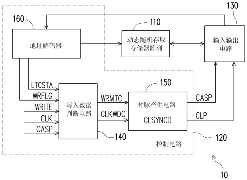
[0076] Please refer to figure 1 , figure 1 is a schematic diagram of a pseudo-static random access memory 10 according to an embodiment of the present invention. The pseudo-SRAM 10 includes a DRAM array 110 , a control circuit 120 , and an input-output circuit 130 . The DRAM array 110 includes a plurality of word lines and a plurality of memory cells (not shown) for storing data, and the present invention does not limit the architecture of the DRAM array. The control circuit 120 is coupled to the DRAM array 110 , and the control circuit 120 includes a write data determination circuit 140 , a clock generation circuit 150 and an address decoder 160 . The address decoder 160 is coupled to the write data judging circuit 140, the DRAM array 110, and the I / O circuit 130. The address decoder 160 can generate a counting start signal LTCSTA and a write flag signal WRFLG corresponding to the execution operations, and The count start signal LTCSTA and the write flag signal WRFLG are p...


PUM


Abstract

The invention provides a control circuit and a control method thereof suitable for a pseudo static random access memory, and the control circuit comprises a write-in data judgment circuit and a clock pulse generation circuit. The write-in data judgment circuit counts and compares the number of data input times of the pseudo-static random access memory with the actual number of data write-in times to generate a write-in matching signal, and generates a write-in counting clock pulse signal according to the counting operation of the number of data input times of the pseudo-static random access memory. The clock pulse generating circuit generates a preamble signal according to the write-in matching signal and the write-in counting clock pulse signal, and generates a row address gating clock pulse signal and a control signal according to the preamble signal. The clock generating circuit determines whether to dynamically delay the preamble signal to delay or omit the pulse of the row selection line signal according to the write matching signal and the write counting clock signal.

Description

technical field [0001] The present invention relates to a control circuit and a control method applied to a memory device, in particular to a control circuit and a control method applied to a pseudo-static random access memory, which are used to generate a row address strobe clock signal and a control signal for Pseudo-SRAM generates row select line signals. Background technique [0002] As the level of integration of semiconductor memory elements becomes higher and higher, there is a demand for higher speed, and static random access memory (SRAM) and dynamic random access memory (DRAM) are used as high-speed memory. Demand for pseudo static random access memory (pSRAM) with the advantages of DRAM continues to increase, especially in mobile devices. [0003] In Pseudo-SRAM, DRAM needs to perform a self-refresh operation because there is no refresh command issued by the user. Existing pseudo-SRAMs use counters to switch between synchronous and asynchronous modes. In the as...

Claims


Application Information

Patent Timeline
IPC IPC(8): G11C11/413G11C7/22H03K21/02
CPCG11C11/413G11C7/22H03K21/02
Inventor 森郁
Owner WINBOND ELECTRONICS CORP