Protection device and circuit protection apparatus containing the same

一种保护元件、电路保护的技术,应用在保护元件及其电路保护装置领域,能够解决含Pb焊料使用限制等问题,达到降低电阻值的效果

Pending Publication Date: 2021-06-18
POLYTRONICS TECH CORP
View PDF12 Cites 0 Cited by
  • Summary
  • Abstract
  • Description
  • Claims
  • Application Information

AI Technical Summary

Problems solved by technology

However, according to the RoHS (Restriction of Hazardous Substances Directive) environmental directives, the use of Pb-containing solder will be restricted

Method used


Image

  • Protection device and circuit protection apparatus containing the same
  • Protection device and circuit protection apparatus containing the same
  • Protection device and circuit protection apparatus containing the same

Examples


Embodiment Construction

[0044] In order to make the above and other technical contents, features and advantages of the present invention more comprehensible, the following specifically cites relevant embodiments, together with the accompanying drawings, for a detailed description as follows.

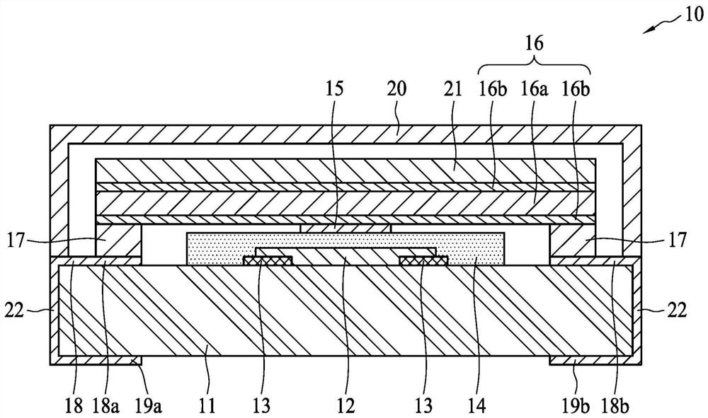
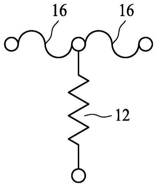
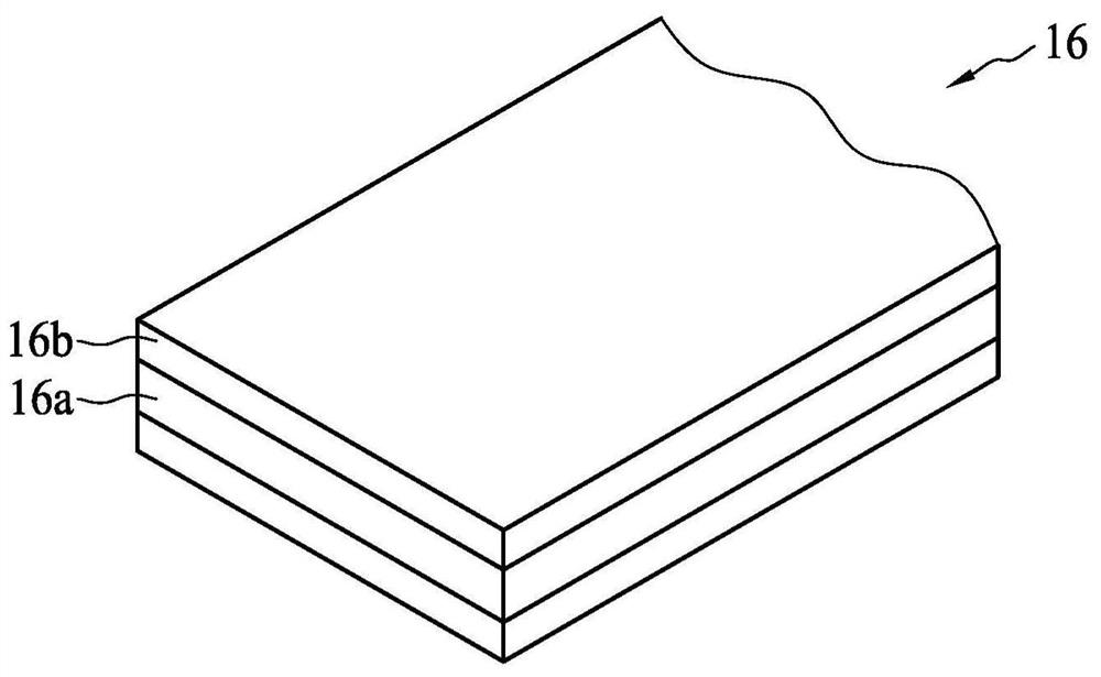
[0045] figure 1 A structural diagram showing a protection element 10 according to an embodiment of the present invention. The protection element 10 has a substrate 11 , a heating element 12 , a heating electrode 13 , an insulating layer 14 , an intermediate electrode 15 , a fuse 16 , solder 17 , an electrode layer 18 , lower electrodes 19 a and 19 b and a cover 20 . The outer edge of the outer cover 20 is disposed on the surface of the substrate 11 to provide an inner space for accommodating the heating element 12 and the fuse element 16 . The substrate 11 is usually a planar insulating substrate. The heating element 12 is disposed on the substrate 11 , and its two ends are electrically connected to the left ...


PUM

PropertyMeasurementUnit
melting pointaaaaaaaaaa

Abstract

A protection device comprises a substrate, a fusible element and a heating element. The substrate comprises a first electrode and a second electrode on its surface. The fusible element is disposed on the substrate and connects to the first electrode and the second electrode at two ends. The fusible element comprises a first metal layer and a second metal layer disposed on the first metal layer. The second metal layer has a lower melting point than that of the first metal layer. The heating element is disposed on the substrate. In the event of over-voltage or over-temperature, the heating element heats up to melt and blow the fusible element. The second metal layer is 40-95% of the fusible element in thickness.

Description

Technical field [0001] The present invention relates to a protection element used in electronic devices and a circuit protection device including the protection element, and in particular to a protection element and a circuit protection device having the function of preventing over-voltage, over-current or over-temperature. Background technique [0002] Protection elements that cut off overcurrent are well known, and current fuses (fuses) made of low-melting point metals such as lead, tin, silver, bismuth, and copper are widely known. Later, in terms of preventing overcurrent and overvoltage, protective elements were continuously developed, which included sequentially stacking a heating layer and a fusible element on a planar substrate. The heating layer will generate heat during overvoltage, and the heat will be transferred upward from the bottom, heating and melting the fuse, thereby cutting off the current flowing through it to protect related circuits or electronic devic...

Claims


Application Information

Patent Timeline
Patent Type & Authority Applications(China)
IPC IPC(8): H01H85/06
CPCH01H85/06H01H85/0065H01H85/463H01H85/11H01H2085/0414H01H2085/466H01H83/20H01H37/761H01H85/046H01H85/08H01H2085/0555
Inventor 苏聪敏陈家茂王绍裘
Owner POLYTRONICS TECH CORP
Why Eureka
Try Eureka