Refrigeration type photoelectric balance detector

A balanced detector and photoelectric detection technology, applied in the field of laser detection, can solve the problems of poor integration and high cost, achieve the effect of reducing cost and volume, and suppressing common mode noise

Pending Publication Date: 2021-06-18
西安中科迅捷光电科技有限公司
View PDF0 Cites 1 Cited by
  • Summary
  • Abstract
  • Description
  • Claims
  • Application Information

AI Technical Summary

Problems solved by technology

But at this stage, domestic research on balanced detectors is still in its infancy, and most of them use discrete optoelectronic devices to achieve a single balanced detection, with poor integration and high cost.

Method used


Image

  • Refrigeration type photoelectric balance detector
  • Refrigeration type photoelectric balance detector
  • Refrigeration type photoelectric balance detector

Examples


Embodiment Construction

[0026] The present invention will be described in further detail below.

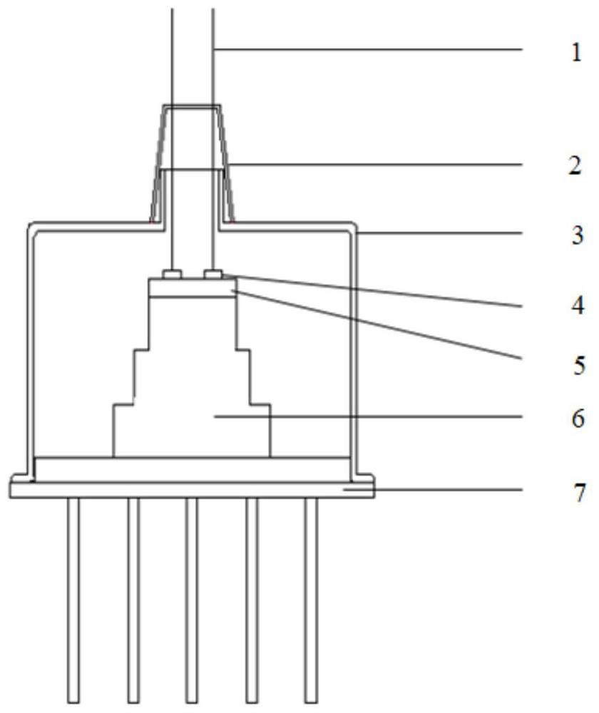
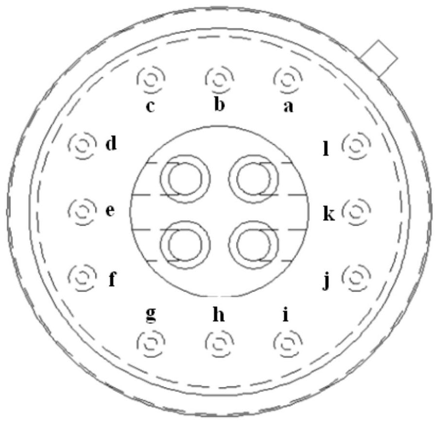
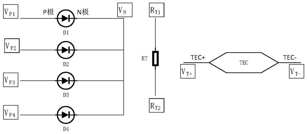
[0027] see Figure 1 to Figure 3 , a cooling type photoelectric balance detector, comprising:

[0028] The input optical fiber 1 is fixed on the cap 3 and is used for inputting four modulation signals.

[0029] The tube cap 3 is fixed on the tube base 7 for encapsulating all components.

[0030] The tube base 7 is located at the bottom of the three-stage TEC refrigeration sheet 6 and is used for fixing the three-stage TEC refrigeration sheet 6 and the tube cap 3 .

[0031] The three-stage TEC cooling plate 6 is located between the circuit board 5 and the tube socket 7, and is used for cooling the balance detector to reach the required working temperature.

[0032] The balanced detector body is pasted on the circuit board 5 and coupled with four optical fibers for converting the modulation signals input by the four optical fibers into electrical signals for output.

[0033] Wherein, the balance detect...


PUM


Abstract

The invention discloses a refrigeration type photoelectric balance detector. The detector comprises an input optical fiber, a protective sleeve, a tube cap, a photoelectric detection chip, a circuit board, a three-stage TEC refrigeration sheet and a tube seat, wherein the three-stage TEC refrigeration sheet is fixedly connected to the top of the tube base, the circuit board is fixed to the top of the three-stage TEC refrigeration sheet, the photoelectric detection chip is fixed to the top of the circuit board, the tube cap sleeves the three-stage TEC refrigeration sheet, the circuit board and the photoelectric detection chip, the bottom of the tube cap is fixed to the tube base, the input optical fiber is fixed to the top of the tube cap, an end portion of the input optical fiber is connected to the photoelectric detection chip, and the protective sleeve is sleeved on the top of the pipe cap and the input optical fiber. According to the detector, integration of a plurality of balance detectors is realized, and the balance detectors work at a specified temperature.

Description

technical field [0001] The invention belongs to the technical field of laser detection, and in particular relates to a cooling type photoelectric balance detector. Background technique [0002] With the rapid development of science and technology, the traditional intensity modulation / direct detection (IM / DD) technology has been unable to meet people's urgent needs for high-speed, long-distance, and large-capacity space optical communications. Coherent optical communication has attracted people's attention due to its many advantages such as high sensitivity, long relay distance, strong anti-interference ability, good communication security performance, and suitability for various modulation formats. It is an important means to realize high-speed space optical communication in the future. Coherent optical communication has become a research hotspot in modern optical communication due to its advantages of high sensitivity, good selectivity, large communication capacity, and mul...

Claims


Application Information

Patent Timeline
Patent Type & Authority Applications(China)
IPC IPC(8): H01L25/04H01L31/02G02B6/43G01S7/02
CPCG01S7/02G02B6/43H01L25/042H01L31/02
Inventor 范建强陈幸李鸣黄佩邢丹
Owner 西安中科迅捷光电科技有限公司
Why Eureka
Try Eureka