
Heat-dissipating member and manufacturing method for same

A manufacturing method and component technology, applied in the field of heat dissipation components and their manufacturing, can solve problems such as reduced thermal conductivity, and achieve the effect of improving manufacturing stability

Active Publication Date: 2021-06-18
DENKA CO LTD
View PDF12 Cites 2 Cited by
  • Summary
  • Abstract
  • Description
  • Claims
  • Application Information

AI Technical Summary

Problems solved by technology

However, when the surface of the heat dissipation member that is in contact with other components is concave or has a large number of fine unevenness, there is a problem that a gap is generated between the heat dissipation member and other components, resulting in a decrease in thermal conductivity.

Method used


Image

  • Heat-dissipating member and manufacturing method for same
  • Heat-dissipating member and manufacturing method for same
  • Heat-dissipating member and manufacturing method for same

Examples


Embodiment 1

[0175] (Manufacture of silicon carbide porous body)

[0176] Silicon carbide powder A (manufactured by Pacific Blue Dam Co., Ltd.: NG-150, average particle diameter: 100 μm) 300 g, silicon carbide powder B (manufactured by Yakushima Denko Co., Ltd.: GC-1000F, average particle diameter: 10 μm) 150 g It was mixed with 30 g of silica sol (manufactured by Nissan Chemical Industry Co., Ltd.: Snowtex) with a stirring mixer for 30 minutes. The obtained mixture was put into a mold of 178 mm×128 mm×5.5 mm, and press-molded at a pressure of 10 MPa. This was calcined at a temperature of 900° C. for 2 hours in the air to obtain a silicon carbide porous body.

[0177] For the following process, 30 sheets of the same silicon carbide porous body were fabricated.

[0178] Both sides of the porous silicon carbide body were sandwiched between plates made of stainless steel (SUS304) with a size of 210 mm×160 mm×0.8 mm, and 30 sheets were laminated. Furthermore, after arranging iron plates wit...

Embodiment 2~7

[0199] Except for changing the length of the long side and the short side of the heat dissipation member, and the bending shape of the pressing punch and the pressing die in the above (impartment of bending), the heat dissipation member was produced in the same manner as in Example 1. Then, it carried out similarly to Example 1, and measured various numerical values.


PUM

PropertyMeasurementUnit
particle sizeaaaaaaaaaa
bending strengthaaaaaaaaaa
thicknessaaaaaaaaaa

Abstract

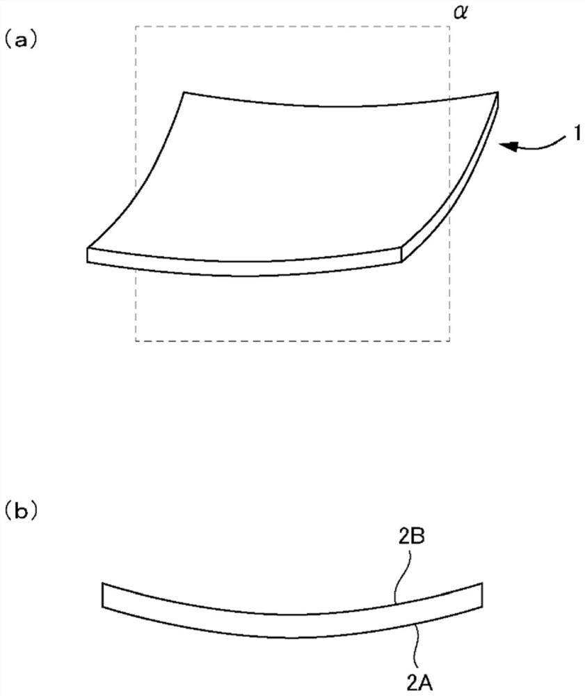
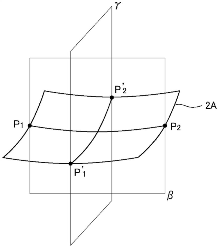
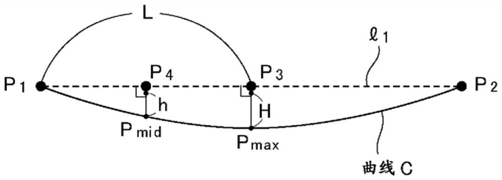
The present invention relates to a substantially rectangular plate-shaped heat-dissipating member provided with a metal-silicon carbide composite comprising Al or Mg. One of the main surfaces of the heat-dissipating member curves in a convex manner to the exterior of the heat-dissipating member, and the other main surface curves in a convex manner to the interior of the heat-dissipating member. In a curved line C formed by the other main surface when the heat-dissipating member is viewed in a cross-sectional view at a cross-section that is roughly perpendicular to the heat-dissipating member and passes through both central points of the two short edges of the other main surface, (2h / L) / (H / L) is at least 1.1, wherein a straight line passing through the two end points P1 and P2 is l1, the point on the curved line C where the distance from l1 is the greatest is P max, an intersection point between l1 and a perpendicular line coming down from Pmax to l1 is P3, the central point of the P1 P3 line part is P4, an intersection point between the curved line C and a straight line that passes through P4 and is perpendicular to l1 is Pmid, the length of the P1 P3 line part is L, the length of the P3 Pmax line part is H, and the length of the P4 Pmid line part is h.

Description

technical field [0001] The present invention relates to a heat dissipation member and a manufacturing method thereof. More specifically, it relates to a plate-shaped heat dissipation member provided with a metal-silicon carbide composite containing aluminum or magnesium, and a method for manufacturing the same. Background technique [0002] In recent years, heat dissipation members made of metal-silicon carbide composites have gradually been used instead of conventional copper as heat dissipation members for power modules for electric vehicles and electric railways. [0003] As the metal of the metal-silicon carbide composite, aluminum and its alloys are often used. [0004] The heat dissipation member is often used in conjunction with other components (for example, heat dissipation fins and heat dissipation units), and the properties of the joint portion are important. [0005] For example, when joining the heat dissipation member to another component, the heat dissipatio...

Claims


Application Information

Patent Timeline
Patent Type & Authority Applications(China)
IPC IPC(8): H01L23/36C04B41/88
CPCC04B41/88H01L23/3736H01L21/4871H01L21/4878C04B41/009C04B41/4523C04B41/52C04B41/90C04B35/565C04B38/00C04B41/5155C04B41/4541C04B41/5093C04B41/5144C04B41/515C04B41/522B28B3/025C04B35/575C04B2235/3418C04B2235/3826C09K5/14F28F21/04F28F21/089H05K7/2039F28F2215/10F28F2215/04
Inventor 后藤大助太田宽朗
Owner DENKA CO LTD
Learn More