
Drive apparatus, compressor, and air conditioner

A driving device and control device technology, applied to compressors, compressors, compressors with reversible cycles, etc., to achieve high reliability, high reliability, and ensure high reliability

Pending Publication Date: 2021-06-18
MITSUBISHI ELECTRIC CORP
View PDF1 Cites 0 Cited by
  • Summary
  • Abstract
  • Description
  • Claims
  • Application Information

AI Technical Summary

Problems solved by technology

[0003] However, rare earth magnets have the property that the higher the temperature, the easier it is to demagnetize

Method used


Image

  • Drive apparatus, compressor, and air conditioner
  • Drive apparatus, compressor, and air conditioner
  • Drive apparatus, compressor, and air conditioner

Examples


Embodiment Construction

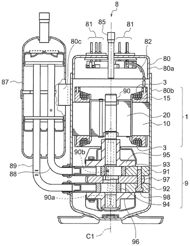
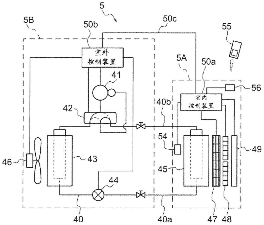
[0046] Hereinafter, a drive device, a compressor, and an air conditioner according to embodiments of the present invention will be described with reference to the drawings. The drive device of the embodiment is a device that drives a motor. The compressor of the embodiment is a device including a motor and the driving device. The air conditioner of embodiment is a device provided with a compressor. The following embodiments are merely examples, and various changes can be made within the scope of the present invention.

[0047]

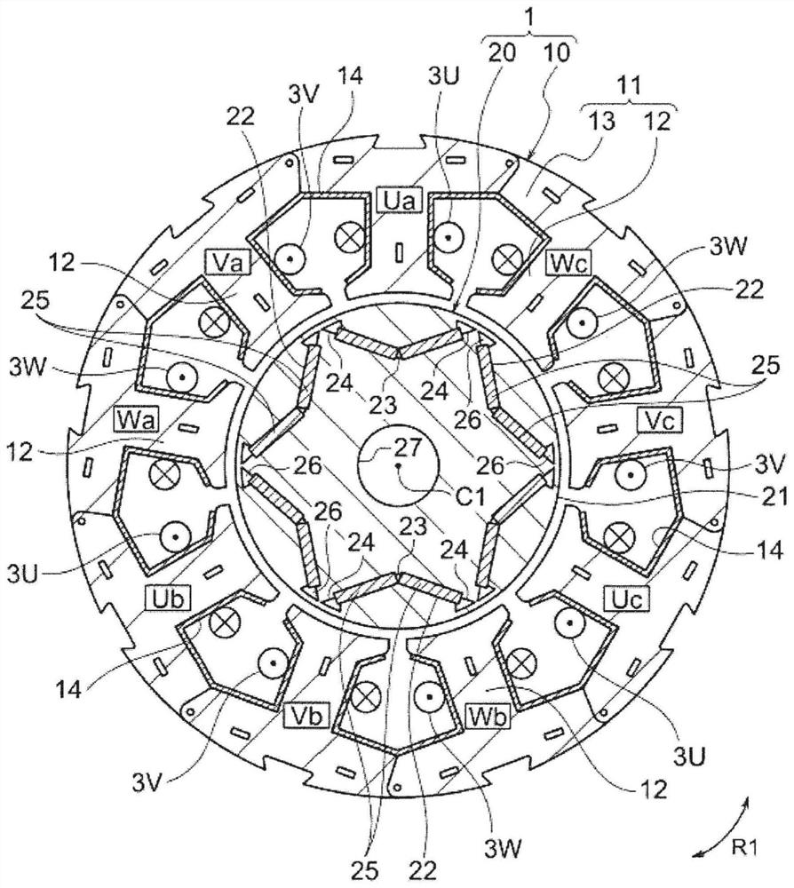
[0048]First, an example of a motor driven by the drive device according to the embodiment of the present invention will be described. figure 1 It is a sectional view schematically showing the structure of the motor 1 . figure 1 A cross section perpendicular to the rotation axis C1 of the rotor 20 is shown. like figure 1 As shown, the motor 1 is a permanent magnet embedded motor. The motor 1 is embedded in a compressor, for example. The motor 1...


PUM


Abstract

A drive apparatus (100a) drives a motor (1) having a rotor provided with a neodymium rare earth magnet. The drive apparatus (100a) is provided with: an inverter (103) that drives the motor (1) at variable speed by performing weak magnetic field control; a first detection unit (201) that outputs a first detection signal (D1) corresponding to a motor drive current to be supplied to the motor (1); a protection level setting unit (70) that sets an over-current protection level; a second detection unit (202) that outputs a second detection signal (D2) corresponding to the drive state of the motor (1); and a control device (500). Immediately after the motor drive current corresponding to the first detection signal has exceeded the over-current protection level, the control device (500) performs first control for lowering the motor drive current. When the protection level setting unit (70) lowers the over-current protection level to a new current level on the basis of the second detection signal, the control device (500) performs second control for lowering the motor drive current to a level lower than the new current level.

Description

technical field [0001] The present invention relates to a driving device for driving a motor, a compressor having the motor and the driving device, and an air conditioner having the compressor. Background technique [0002] Conventionally, a drive device for driving a rare-earth magnet motor (also referred to as a "permanent magnet motor" or "motor") having a rotor with a rare-earth magnet includes: ) to supply the motor drive current; and the control device performs PWM (Pulse Width Modulation, pulse width modulation) control on the inverter. Also proposed is a driving device having a protection function of reducing (including cutting off) the motor driving current immediately after the motor driving current supplied to the motor exceeds a threshold value (ie, a set value) (for example, refer to Patent Document 1). The threshold is the current level used to protect the motor from overcurrent, that is, the upper limit value of the motor drive current used to prevent the rar...

Claims


Application Information

Patent Timeline
IPC IPC(8): H02P23/00H02P25/18H02P29/62H02K1/27
CPCH02K1/2766H02K1/02H02K1/148H02K11/21H02K11/25H02K11/27H02K3/325H02K7/14H02K2213/03F25B13/00F25B49/02F25B2700/2104F25B2600/07G01R31/343H02P25/184H02P29/60H02P29/032H02P29/027H02P2207/05H01F1/057F25B31/026G01R19/16571G01R19/32H01F1/053H02K1/276H02P27/08
Inventor 仁吾昌弘
Owner MITSUBISHI ELECTRIC CORP
Learn More