Graphene film cutting equipment

A cutting equipment, graphene technology, applied in stone processing equipment, stone processing tools, cleaning methods and appliances, etc., can solve the problem of carbon powder scratching the end face of graphene film, and achieve the effect of increasing the spraying force

Inactive Publication Date: 2021-06-22
鄢丽媛
View PDF5 Cites 1 Cited by
  • Summary
  • Abstract
  • Description
  • Claims
  • Application Information

AI Technical Summary

Problems solved by technology

[0003] Based on the inventor's discovery above, the existing graphene film cutting equipment mainly has the following disadvantages, for example: when the graphene film is cut, a large amount of carbon powder will be produced by the cutter rubbing the end face of the film , the toner placed on the end face of the film needs to be taken away by the airflow, and part of the toner will be adsorbed on the end face of the film due to the static electricity generated by the friction between the cutter and the film, so that the toner will be caught when the film is stacked and stored. Friction between the films causes carbon powder to scratch the end face of the graphene film

Method used


Image

  • Graphene film cutting equipment
  • Graphene film cutting equipment
  • Graphene film cutting equipment

Examples


Embodiment 1

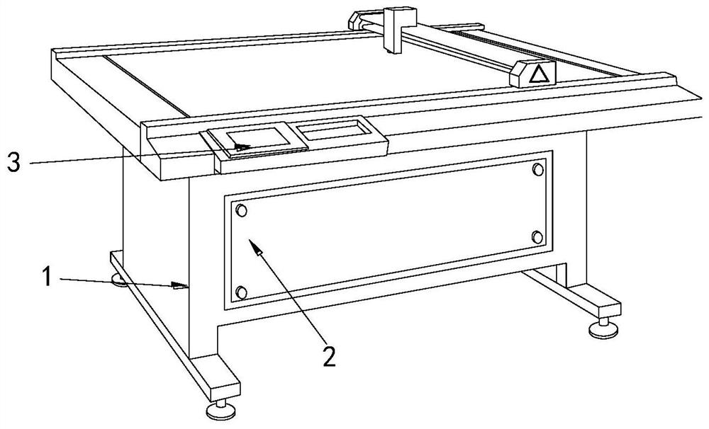
[0028] Example 1: Please refer to Figure 1-Figure 6 , the specific embodiments of the present invention are as follows:

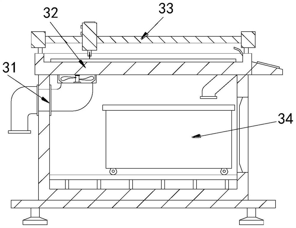
[0029] Its structure includes a main body 1, a box door 2, and a control panel 3. The front end of the main body 1 is provided with a box door 2, and the control panel 3 is installed on the top front end of the main body 1. The main body 1 includes an air intake pipe 31, a cutting table 32. Cutting block 33, dust collection box 34, the air intake pipe 31 is arranged at the side end of the main body 1, the cutting table 32 is installed at the top of the main body 1, and the cutting block 33 is engaged with both ends of the top of the main body 1 , the dust box 34 is arranged at the inner side end of the main body 1 .

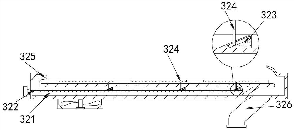
[0030] The cutting table 32 includes a ventilation groove 321, a pull rod 322, a guide block 323, a turning device 324, an air injection device 325, and a feeding pipe 326. The ventilation groove 321 is arranged inside the cutting table 32, ...

Embodiment 2

[0035] Example 2: Please refer to Figure 7-Figure 9 , the specific embodiments of the present invention are as follows:

[0036] The air injection device 325 includes a rubber ball c1, a rear flow hole c2, a splitter c3, and a dispersion sheet c4. Arranged at the rear end of the rubber ball c1, the splitter c3 is provided with three, and vertically arranged at the inner rear end of the air injection device 325, and the dispersion sheet c4 is provided with two, and is located behind two splitters c3 Right in the middle, the angle formed between the dispersing pieces c4 is 30 degrees, which is conducive to stretching the rubber ball c1 through the impact of the air flow, and then using the rubber ball c1 to shrink to eject the internal air to the rear flow hole c2, Increase the jet intensity of the airflow.

[0037] The dispersing piece c4 includes a dispersion body c41, a rotating shaft c42, a rewinding spring c43, a limit block c44, and a guide groove c45. The end surface o...


PUM

PropertyMeasurementUnit
angleaaaaaaaaaa

Abstract

The invention discloses graphene film cutting equipment which structurally comprises a main body, a box door and a control panel. The box door is arranged at the front end of the main body, the control panel is installed at the front end of the top of the main body, the main body comprises an air inlet pipe, a cutting table, a cutting block and a chip collecting box, and the cutting table comprises a vent groove, a pull rod, a guide block, a turnover device, an air injection device and a discharging pipe; the turnover device comprises a movable groove, a supporting plate, an upper ejector rod and an air injection groove; the movable groove comprises a groove body, an air guide block, a supporting frame and a supporting strip; and the supporting strip comprises an air guide sheet, an air outlet hole and a filter screen. According to the graphene film cutting equipment, the guide block is driven by the pull rod to move forwards, so that the turnover device can drive a graphene film to be inclined, airflow can fully impact carbon powder on the end surface of the film, the carbon powder is guided into the discharging pipe, the carbon powder can fall into the chip collecting box to be collected, the carbon powder is prevented from being attached to the end face of the thin film due to static electricity, and the situation that the thin film is scratched during storage is avoided.

Description

technical field [0001] The invention relates to the field of graphene processing equipment, in particular to a graphene film cutting equipment. Background technique [0002] Graphene usually adopts vapor deposition method to precipitate graphene powder to form graphene film, and graphene film needs to be cut during processing, and the graphene film needs to be cut by a film cutting machine when cutting, and the graphene The film is cut into fragments of consistent size to facilitate the subsequent application of the graphene film. [0003] Based on the inventor's discovery above, the existing graphene film cutting equipment mainly has the following deficiencies, for example: when the graphene film is cut, the cutter rubs the end face of the film to produce a large amount of carbon powder , the toner placed on the end face of the film needs to be taken away by the airflow, and part of the toner will be adsorbed on the end face of the film due to the static electricity genera...

Claims


Application Information

Patent Timeline
Patent Type & Authority Applications(China)
IPC IPC(8): B28D1/22B28D7/04B28D7/02B28D7/00B08B5/02B08B13/00
CPCB28D1/22B28D7/04B28D7/02B28D7/00B08B5/02B08B13/00
Inventor 鄢丽媛
Owner 鄢丽媛
Why Eureka
Try Eureka