Eureka AIR delivers breakthrough ideas for toughest innovation challenges, trusted by R&D personnel around the world.

Gate groove construction device and gate groove construction method

A construction device and door slot technology, which is applied in water conservancy projects, sea area engineering, hydroelectric power generation, etc., can solve the problems of inability to cooperate with sliding forms, long construction period, and low efficiency of door slots, so as to shorten the construction period, improve construction efficiency, The effect of reducing friction

Active Publication Date: 2021-06-22
CHENGDU ALANGTECH
View PDF7 Cites 1 Cited by
  • Summary
  • Abstract
  • Description
  • Claims
  • Application Information

AI Technical Summary

Problems solved by technology

[0008] The purpose of the present invention is: in view of the prior art, when the door slot construction device is used to construct the door slot, it cannot be used in conjunction with the sliding form, and can only be used in conjunction with templates such as turning formwork and climbing formwork, resulting in low efficiency in the construction of the door slot. To solve the problem of long construction period, provide a door slot construction device and a door slot construction method

Method used


Image

  • Gate groove construction device and gate groove construction method
  • Gate groove construction device and gate groove construction method
  • Gate groove construction device and gate groove construction method

Examples


Embodiment 1

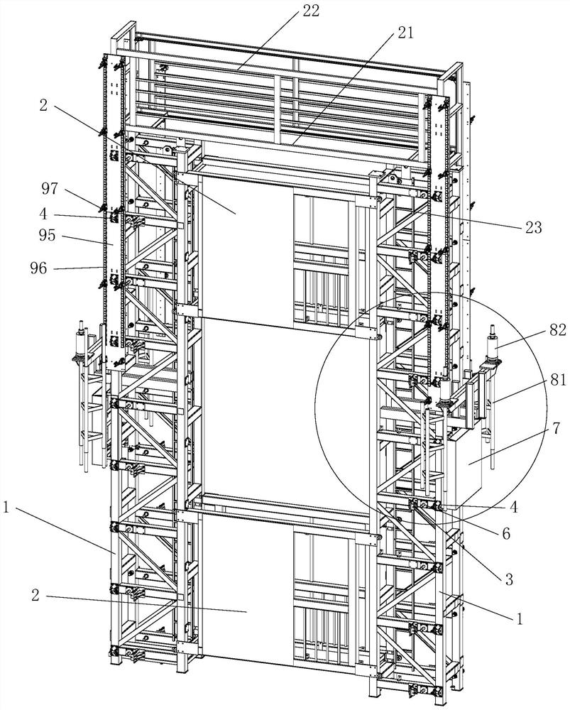
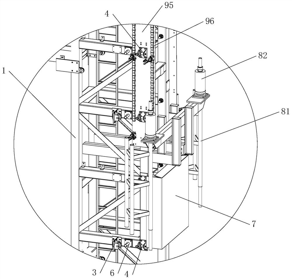
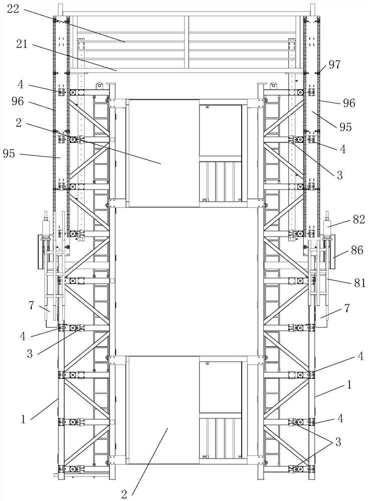
[0108] This embodiment provides a door slot construction device, see Figure 1-7 , including two uprights 1 corresponding to the door slots on both sides and several beam modules 2 connected between the two uprights 1, the sides of the uprights 1 are fixedly connected with several positioning supports, and the positioning supports are used for positioning support Corresponding to the door slot track 11, the positioning support includes a side guide support device 3 and a front support device, the side guide support device 3 is used for sliding contact or rolling contact with the side of the corresponding door slot track 11, and the front support The device is used for sliding contact or rolling contact with the front of the corresponding door slot track 11, and the column 1 is also provided with a fixing device for installing the door slot track 11 to be installed;

[0109] When the column 1 is under the action of lifting force, both the positioning support member and the fixi...

Embodiment 2

[0140] This embodiment provides a door slot construction device, which differs from the door slot construction device described in Embodiment 1 in that when the door slot track 11 to be installed is a material capable of generating magnetic attraction with magnetic components, such as steel structure, the fixing device can adopt a magnetic member, the magnetic member is connected to the column 1 along the longitudinal direction of the column 1, and the magnetic member is used to fix the door slot track 11 . The door slot track 11 is fixed by magnetic attraction to ensure the installation accuracy of the door slot track 11 to be installed. At the same time, under the action of the lifting force, the magnetic member can also slide relative to the door slot track 11 to meet the upward lifting of the door slot construction device. condition. Of course, the door slot track 11 made of steel can also use the compactor 9 in Embodiment 1 as a fixing device.

Embodiment 3

[0142] This embodiment provides a door slot construction device, which differs from the door slot construction device described in Embodiment 1 in that, see Figure 24-25 , the lifting point 84 is not set on the lifting beam 83, and the lifting beam 83 is not connected to the column 1 by a flexible connection such as a steel rope, but a lifting frame 831 is supported on the lifting beam 83, and the lifting Frame 831 is connected with described column 1, and the quantity of lifting frame 831 is determined according to actual situation, and described lifting frame 831 is positioned at the outside of described lifting beam 83 and is provided with lifting frame stopper 832, and described lifting frame stopper 832 has limit position. effect. By placing the lifting frame 831 connected to the column 1 above the lifting beam 83, the lifting frame 831 and the lifting beam 83 are not connected, and the lifting frame 831 is supported by the lifting beam 83. When the lifting beam 83 is li...


PUM


Abstract

The invention relates to a gate groove construction device. The gate groove construction device comprises two stand columns corresponding to gate grooves in the two sides correspondingly; and each stand column is provided with a fixing device used for installing a to-be-installed gate groove rail and a plurality of positioning supporting pieces. By improving the positioning supporting pieces and the fixing devices, the positioning supporting pieces support the gate groove rails in a sliding contact or rolling contact manner, friction force between the positioning supporting pieces on the stand columns and the gate groove rails is reduced by reducing friction of sliding contact or reducing friction of rolling contact, and the situation that the positioning supporting pieces and the gate groove rails are stuck when the stand columns are matched with a sliding formwork to be lifted is avoided; and the fixing devices can move along the to-be-poured gate groove rails, when the gate groove construction device is matched with the sliding formwork to be used, the precision of gate groove construction of the gate groove construction device cannot be influenced by sliding formwork construction, the gate groove construction device can be lifted together with the sliding formwork, the gate grooves can be continuously constructed through the sliding formwork and the gate groove construction device, the gate groove construction efficiency is improved, and the overall construction period is shortened.

Description

technical field [0001] The invention relates to the technical field of gate construction, in particular to a gate slot construction device and a gate slot construction method. Background technique [0002] In water conservancy and hydropower engineering projects, the gate is used to close and open the control facility of the discharge (discharge) channel. As an important part of the hydraulic structure, it can be used to intercept the water flow, control the water level, adjust the flow, discharge sediment and float things etc. The gate mainly consists of three parts: (1) the main movable part, which is used to close or open the opening, commonly known as the gate, also known as the door leaf; (2) the embedded part; (3) the opening and closing equipment. The embedded parts include main rail, anti-rail, hinge seat, lintel, bottom sill, water stop seat, etc. They are buried around the opening, firmly connected with the concrete of the hydraulic structure with anchor bars, and...

Claims


Application Information

Patent Timeline
IPC IPC(8): E02B7/20E02B7/28E02B7/30
CPCE02B7/20E02B7/28E02B7/30Y02E10/20
Inventor 彭智祥冯梦林王洲科郭文彬何建国张欣
Owner CHENGDU ALANGTECH
Why Eureka
Eureka Blog
Learn More