Centrifugal compressor of hydrogen circulating pump
A circulating pump, centrifugal technology, applied in the components, pump, pump control and other directions of the pumping device for elastic fluid, can solve the problem of hydrogen circulating pump freezing and so on
- Summary
- Abstract
- Description
- Claims
- Application Information
AI Technical Summary
Problems solved by technology
Method used
Image
Examples
Embodiment 1
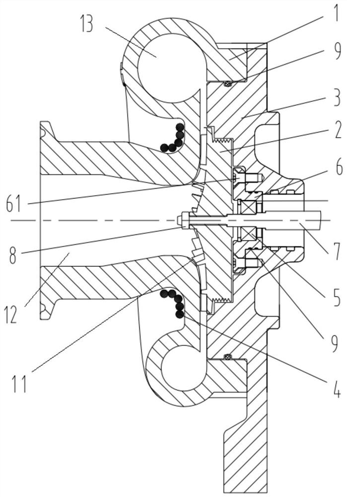
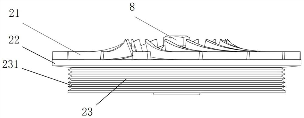
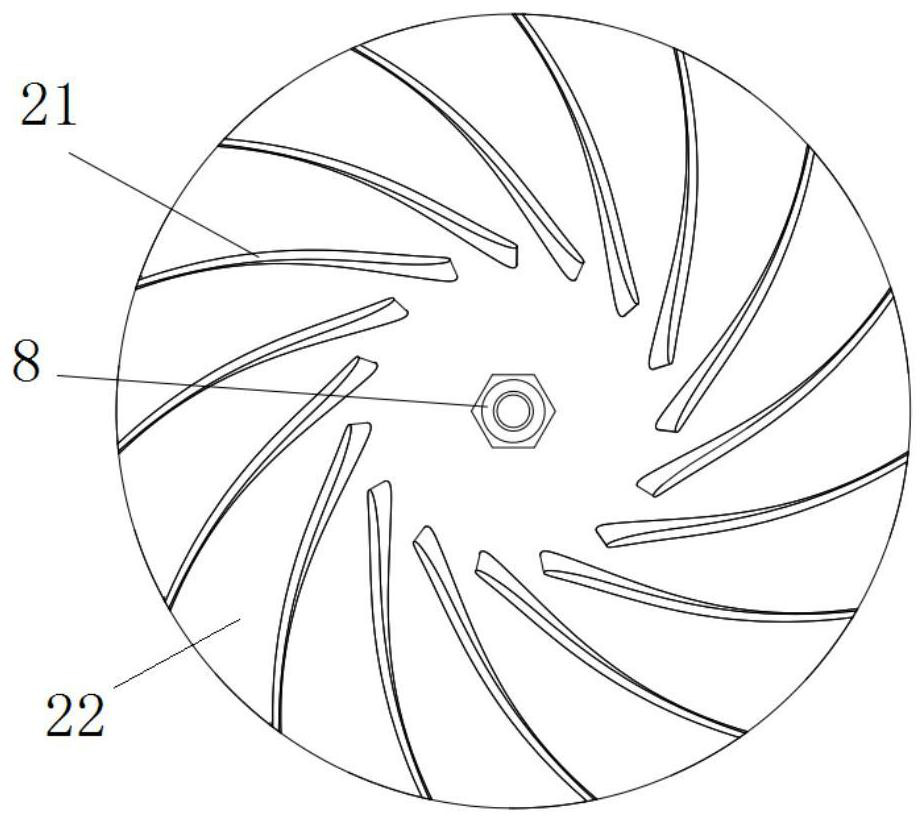
[0028] A centrifugal compressor for a hydrogen circulation pump, such as figure 1 As shown, it includes a fixedly connected volute 1 and an adapter seat 3, and also includes an impeller 2 arranged inside the volute 1 and the adapter seat 3; the volute 1 includes an axial The air inlet 12 and the tangential exhaust pipe 13 arranged in its circumferential direction are sealed with a sealing ring 9 (such as an O-ring) between the volute 1 and the adapter seat 3 to prevent hydrogen leakage. The impeller 2 is as Figure 2-3 As shown, it includes a blade 21, a blade carrying disk 22 and a sealing disk 23, and the blade 21 is evenly arranged on the end of the blade carrying disk 22 facing the axial air inlet 12 around the rotation axis of the impeller 2, so The sealing disc 23 is coaxially arranged on the other end of the blade bearing disc 22; the blade 21, the blade bearing disc 22 and the sealing disc 23 are generally integrated, and the circumferential surface of the sealing dis...
Embodiment 2
[0036] Different from the above-mentioned embodiments, such as Figure 6 As shown, the impeller shaft hole can be designed as a stepped hole, the first light hole with a short radius is set on the side where the blade carrying plate 22 is located, and the positioning light hole with a long radius is set on the side where the sealing plate 23 is located.
[0037] The free end of the rotating shaft 7 ( Figure 6 The left end of the left end) is provided with a threaded part 71 and a positioning disc 73; the threaded part 71 is screwed out of the shaft hole 24, and after the blade 21 side is screwed and fastened with the fastening nut 8, the positioning disc 73 is just on the The positioning light hole is positioned at the step. At this time, the fastening nut 8 can be a double nut structure, and the fastening nut 8 of the double nut structure is screwed on the threaded part 71 to compress the impeller 2 and the positioning plate 73, so as to prevent the impeller 2 from rotating...
PUM
 Abstract
Description
Claims
Application Information
 - R&D
- Intellectual Property
- Life Sciences
- Materials
- Tech Scout
- Unparalleled Data Quality
- Higher Quality Content
- 60% Fewer Hallucinations
Browse by: Latest US Patents, China's latest patents, Technical Efficacy Thesaurus, Application Domain, Technology Topic, Popular Technical Reports.
© 2025 PatSnap. All rights reserved.Legal|Privacy policy|Modern Slavery Act Transparency Statement|Sitemap|About US| Contact US: help@patsnap.com


