Supercharge Your Innovation With Domain-Expert AI Agents!

Optical device test structure and manufacturing method thereof

A technology for testing structures and optical devices, applied in the testing of single semiconductor devices, optical components, optics, etc., can solve the problems of large volume, small bandwidth, low loss, etc., and achieve the effect of small volume

Inactive Publication Date: 2021-06-22
INST OF MICROELECTRONICS CHINESE ACAD OF SCI
View PDF5 Cites 0 Cited by
  • Summary
  • Abstract
  • Description
  • Claims
  • Application Information

AI Technical Summary

Problems solved by technology

[0004] The advantage of the grating coupler is that it can achieve wafer-level optical coupling, and it can be coupled and tested at any time during the wafer preparation process. The disadvantages are large loss, small bandwidth, and large volume after chip packaging; the advantage of the edge coupler is loss Small size, large bandwidth, and small size after chip packaging. The disadvantage is that it cannot be coupled at the wafer level, and it cannot be coupled and tested at any time during the process to monitor the performance of optical devices at any time. After all processes are completed, each chip needs to be divided into chips Test, chip-level test efficiency is much lower than wafer-level test

Method used


Image

  • Optical device test structure and manufacturing method thereof
  • Optical device test structure and manufacturing method thereof
  • Optical device test structure and manufacturing method thereof

Examples


Embodiment Construction

[0032] Hereinafter, embodiments of the present disclosure will be described with reference to the drawings. It should be understood, however, that these descriptions are exemplary only, and are not intended to limit the scope of the present disclosure. Also, in the following description, descriptions of well-known structures and techniques are omitted to avoid unnecessarily obscuring the concept of the present disclosure.

[0033] Various structural schematic diagrams according to embodiments of the present disclosure are shown in the accompanying drawings. The figures are not drawn to scale, with certain details exaggerated and possibly omitted for clarity of presentation. The shapes of the various regions and layers shown in the figure, as well as their relative sizes and positional relationships are only exemplary, and may deviate due to manufacturing tolerances or technical limitations in practice, and those skilled in the art will Regions / layers with different shapes, s...


PUM


Abstract

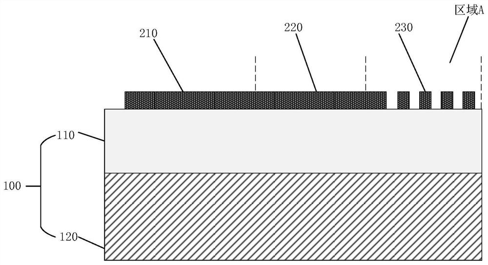
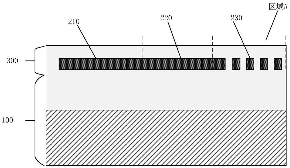
The invention provides an optical device test structure and a manufacturing method thereof. The structure comprises a substrate and a device layer formed on the substrate; the device layer comprises an optical device, an end face coupler and a grating coupler; the optical device is connected with the end face coupler through an optical waveguide; the end face coupler is in coupling connection with the grating coupler; and the grating coupler is located in an area, where a scribing deep groove is to be manufactured, of the substrate. According to the optical device test structure provided by the invention, the advantages of the end face coupler and the grating coupler are combined, and the wafer-level test and chip packaging problems of an optical chip can be solved at the same time.

Description

technical field [0001] The disclosure relates to the technical field of photonic devices, in particular to an optical device testing structure and a manufacturing method thereof. Background technique [0002] Silicon photonics technology uses silicon as the optical medium and uses CMOS (complementary metal oxide semiconductor) technology to develop and integrate optical devices. It is expected to realize low-cost, high-speed optical communication and has broad market application prospects. [0003] One of the key issues inhibiting the widespread application of silicon photonic chips (referred to as photonic chips) is the coupling of optical fibers to photonic chips. The coupling problem with the optical fiber is a problem that any optical chip or product must solve. Silicon waveguide couplers mainly include two types, namely grating couplers and end face couplers. [0004] The advantage of the grating coupler is that it can achieve wafer-level optical coupling, and it can ...

Claims


Application Information

Patent Timeline
IPC IPC(8): G02B6/12G02B6/42G01R31/26
CPCG02B6/12G02B6/4201G02B2006/12147G02B2006/12176
Inventor 杨妍张鹏孙富君唐波李彬刘若男谢玲李志华
Owner INST OF MICROELECTRONICS CHINESE ACAD OF SCI
Features
  • R&D
  • Intellectual Property
  • Life Sciences
  • Materials
  • Tech Scout
  • Unparalleled Data Quality
  • Higher Quality Content
  • 60% Fewer Hallucinations
Learn More