Stannide thermoelectric conversion element and stannide thermoelectric conversion module

A thermoelectric conversion and component technology, which is applied in the manufacture/processing of electrical components, thermoelectric device parts, and thermoelectric devices, etc., can solve the problem of difficulty in generating electricity efficiently, and achieves the goal of suppressing the reduction of power generation performance and the increase of resistance value. Effect

Pending Publication Date: 2021-06-22
ERNST & YOUNG
View PDF8 Cites 0 Cited by
  • Summary
  • Abstract
  • Description
  • Claims
  • Application Information

AI Technical Summary

Problems solved by technology

[0009] When attempting to use Mg-Si-based thermoelectric conversion elements in order to utilize the waste heat of 400°C to 450°C, it is difficult to efficiently generate electricity because it is out of the appropriate temperature range of Mg-Si-based thermoelectric conversion elements

Method used


Image

  • Stannide thermoelectric conversion element and stannide thermoelectric conversion module
  • Stannide thermoelectric conversion element and stannide thermoelectric conversion module
  • Stannide thermoelectric conversion element and stannide thermoelectric conversion module

Examples


Embodiment 1

[0073] [Example] 1. Manufacture of thermoelectric conversion module

[0074] (Example 1)

[0075] (1) Manufacture of thermoelectric conversion elements

[0076] so that the composition becomes Mg 2 Si 0.3 sn 0.7 In this method, Mg, Si, and Sn were measured, and predetermined amounts of Mg, Si, and Sn were mixed to obtain a mixture. The obtained mixture was charged into an induction melting furnace, and then heated and melted under an argon atmosphere. Then, the obtained molten material was cooled to room temperature (about 25 degreeC), and the ingot was produced. The obtained ingot was mechanically pulverized to obtain Mg composed of particles with an average particle diameter of several tens of μm. 2 Si 0.3 sn 0.7 of powder.

[0077] The obtained powder was put into a jig for sintering made of graphite, at 5×10 -3 Sintering was carried out at a sintering pressure of 50 MPa and a sintering temperature of 680° C. under a reduced-pressure atmosphere below Pa. As a res...

Embodiment 2

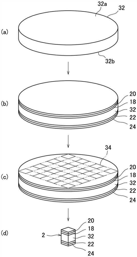
[0091] In addition to polishing the both end surfaces 32a, 32b of the sintered body 32 using diamond paste containing diamond particles with a particle size of 3 μm, the surface roughness (Rz) of the both end surfaces 32a, 32b is set to The thermoelectric conversion module 4 was produced in the same manner as in Example 1 except that the thickness was 4.0±0.2 μm.

Embodiment 3

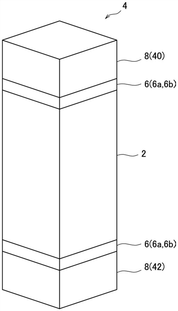
[0093] except as Image 6 As shown, when manufacturing the thermoelectric conversion module, a composite plating layer as a metal layer composed of a Ni plating layer and an Au plating layer is formed on the surface of the electrode material 8 (Cu member) in advance, and a composite plating layer is formed between one end surface of the thermoelectric conversion element 2 and the second end surface of the thermoelectric conversion element 2. Joining is performed with the metal layers (composite plating of Ni plating and Au plating) 48 and 50 present between the first Cu members 60 and between the other end surface of the thermoelectric conversion element 2 and the second Cu member 62. In addition, the thermoelectric conversion module 4 was produced in the same manner as in Example 1.

[0094] That is, Example 3 is a configuration using the non-fluid joint material 6a.

[0095] It should be noted that a Ni plating layer was formed on the surface of the electrode material 8 (me...


PUM

PropertyMeasurementUnit
surface roughnessaaaaaaaaaa
particle diameteraaaaaaaaaa
thicknessaaaaaaaaaa

Abstract

A tin-based thermoelectric conversion module (4) is provided with: a thermoelectric conversion element (2); and an electrode material (8) bonded to the thermoelectric conversion element (2) via the bonding material (6), and the thermoelectric conversion element (2) is provided with: a thermoelectric conversion part (16) containing a thermoelectric material having a structure represented by the general formula Mg2Si1-xSnx (wherein x satisfies the relationship 0.5 < x < 1); ) a tin-based compound having a composition represented by formula (1); and a first diffusion prevention layer (18) located on the surface of the thermoelectric conversion part (16), the first diffusion prevention layer (18) being a tin-based thermoelectric conversion element including a Mo layer (26), and the bonding material (6) being a non-flowable bonding material (6a) having no flowability.

Description

technical field [0001] The invention relates to a tin-based thermoelectric conversion element and a tin-based thermoelectric conversion module. Background technique [0002] A thermoelectric conversion element that converts heat into electricity is used for thermoelectric conversion that generates electricity using waste heat from a heat source portion of various devices. The thermoelectric conversion element is arranged between a pair of electrode materials, thereby forming a thermoelectric conversion module. In this thermoelectric conversion module, one end of the thermoelectric conversion element is heated by waste heat from the heat source of various devices, thereby generating a temperature difference with the other end, and the Seebeck that generates electromotive force corresponding to the temperature difference is utilized. effect to convert thermal energy directly into electrical energy. [0003] Such a thermoelectric conversion module has no movable parts and has...

Claims


Application Information

Patent Timeline
Patent Type & Authority Applications(China)
IPC IPC(8): H01L35/08H01L35/14H02N11/00
CPCH10N10/817H10N10/855H10N10/01H10N10/854
Inventor 坂本达也田口豊
Owner ERNST & YOUNG
Why Eureka
Try Eureka