Welding wheel

A welding machine, contact surface technology, applied in welding equipment, welding equipment, auxiliary welding equipment, etc., can solve problems such as reducing life, increasing current frequency and current intensity not optimal, increasing wheel heating, etc.

Pending Publication Date: 2021-06-25
GAZTRANSPORT & TECHNIGAZ
View PDF0 Cites 0 Cited by
  • Summary
  • Abstract
  • Description
  • Claims
  • Application Information

AI Technical Summary

Problems solved by technology

However, these increases do have the drawback of significantly increasing the heating of the wheel
Indeed, the Applicant has found that the current construction of the wheels is not optimal for withstanding this increase in current frequency and amperage intensity, with the result that their lifespan is reduced, notably due to wear of the wheels

Method used


Image

  • Welding wheel
  • Welding wheel
  • Welding wheel

Examples


Embodiment Construction

[0049] The features, variants and various embodiments of the invention may be related to each other according to various combinations, since they are not mutually incompatible or exclusive. It will be possible to devise variants of the invention comprising only a set of the following features in isolation from other stated features, so long as this selection of features is sufficient to confer a technical advantage or differentiate the invention from the state of the art.

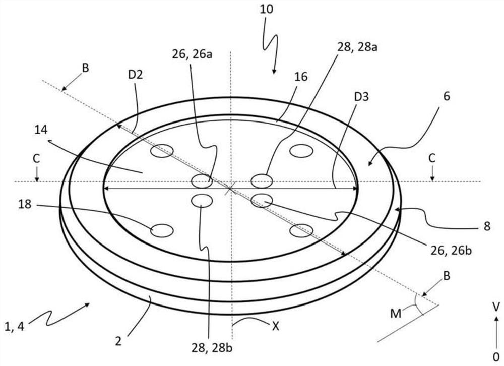
[0050] figure 1 A welding wheel 1 according to the invention is shown. The welding wheel 1 can be used to weld metal sheets together by continuous motion and spot welding. For this purpose, the welding wheel 1 is fixed to the welding machine (in Figure 7 Visible in ), its movement along the metal plate is carried out continuously at a speed greater than or equal to 2.5 m / min. Said movement of the welding machine thus ensures the movement of the wheel 1 and the diffusion of the current inside the wheel 1...


PUM

PropertyMeasurementUnit
diameteraaaaaaaaaa

Abstract

The subject of the invention is a welding wheel (1) for welding metal sheets (52, 54), the wheel (1) comprising a contact surface (2) inscribed within a disk (4) having a diameter (D1) of less than 100 mm, and a cooling system (20) comprising a first cooling circuit (22) and a second cooling circuit (24).

Description

technical field [0001] The field of the invention is that of welding wheels, in particular welding wheels for the seam welding of metal sheets forming the walls of storage tanks for the storage and transport of liquefied natural gas. Background technique [0002] A tank for storing and / or transporting liquefied natural gas (LNG) consists of a tank wall comprising, inter alia, thermal insulation and metal plates to ensure the sealing of said tank wall. In order to fix and fasten the metal sheets to each other, it is known to weld them to each other. In fact, the welding of the metal plates ensures an optimal sealing of the tank and effective fixing of the metal plates to each other. For this purpose, it is known to use a welding machine comprising at least one welding wheel capable of welding metal sheets under the action of an electric current flowing through the wheel. Such welding wheels thus consist of alloys of different metals which exhibit conductive properties compa...

Claims


Application Information

Patent Timeline
Patent Type & Authority Applications(China)
IPC IPC(8): B23K31/02B23K37/00B23K37/02
CPCB23K37/02B23K37/003B23K31/02B23K11/06B23K11/3045B23K11/061B23K11/3054B23K2101/12B23K2101/18
Inventor N.劳雷恩M.比登巴赫S.卡斯特
Owner GAZTRANSPORT & TECHNIGAZ
Why Eureka
Try Eureka