
Semi-automatic hydraulic tool for special-shaped parts

A semi-automatic, parts-based technology, applied in the direction of metal processing machinery parts, positioning devices, manufacturing tools, etc., can solve the problems of unguaranteed size parts falling off, uncontrolled clamping force, slow clamping speed, etc., to achieve low cost and debugging The effect of convenience and part quality control

Pending Publication Date: 2021-06-25
上海华验精密机电科技有限公司
View PDF0 Cites 0 Cited by
  • Summary
  • Abstract
  • Description
  • Claims
  • Application Information

AI Technical Summary

Problems solved by technology

Traditional tooling can only be clamped by manual compression. Not only is the clamping speed slow, but the corresponding clamping force is not controlled. If it is too large, it will deform the force

Method used


Image

  • Semi-automatic hydraulic tool for special-shaped parts
  • Semi-automatic hydraulic tool for special-shaped parts
  • Semi-automatic hydraulic tool for special-shaped parts

Examples


Embodiment Construction

[0019] The following will clearly and completely describe the technical solutions in the embodiments of the present invention with reference to the accompanying drawings in the embodiments of the present invention. Obviously, the described embodiments are only some, not all, embodiments of the present invention. Based on the embodiments of the present invention, all other embodiments obtained by persons of ordinary skill in the art without making creative efforts belong to the protection scope of the present invention.

[0020] In the description of the present invention, it should be noted that the orientation or positional relationship indicated by the terms "vertical", "upper", "lower", "horizontal" etc. is based on the orientation or positional relationship shown in the drawings, and is only In order to facilitate the description of the present invention and simplify the description, it does not indicate or imply that the device or element referred to must have a specific o...


PUM


Abstract

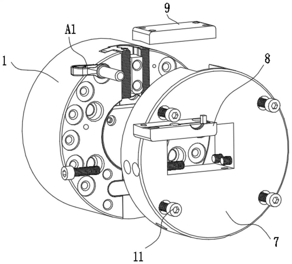
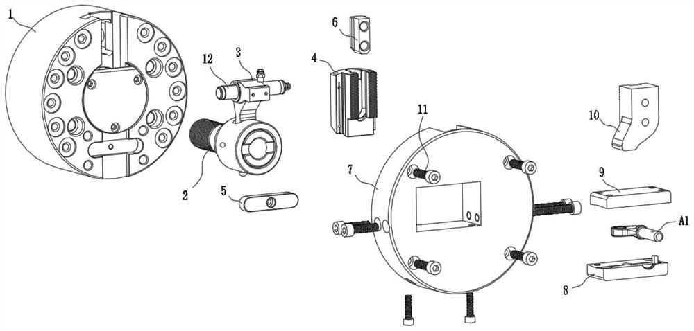
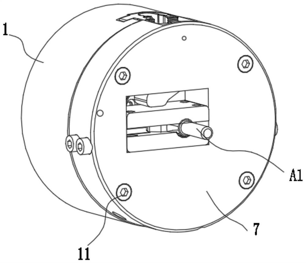
The invention belongs to the field of clamp tools, and particularly discloses a semi-automatic hydraulic tool for special-shaped parts. The semi-automatic hydraulic tool comprises a hydraulic chuck structure arranged on an equipment body and a clamp structure, the hydraulic chuck structure is fixedly connected with the equipment body, and the clamp structure is connected to the hydraulic chuck structure. The hydraulic chuck structure comprises a single-jaw hydraulic chuck body, a chuck pull rod, a chuck cam lever and a chuck movable clamping jaw, the single-jaw hydraulic chuck body is fixedly connected with an equipment flange through a fixed bolt, and a round hole is formed in the center of the single-jaw hydraulic chuck body. The chuck pull rod is arranged on one side of the single-jaw hydraulic chuck body, the rear end of the chuck pull rod is connected with a hydraulic cylinder of the equipment body through threads, a cylinder is arranged at the front end of the chuck pull rod and cooperates with the round hole in the center of the single-jaw hydraulic chuck body, and the chuck pull rod can axially move along with the hydraulic cylinder when the hydraulic cylinder works. The tool is simple in structure and convenient to debug, a hydraulic mechanism is adopted, and clamping force is stable and reliable.

Description

technical field [0001] The invention relates to the field of clamp tooling, in particular to a semi-automatic hydraulic tooling for special-shaped parts. Background technique [0002] Machining refers to the process of changing the shape or performance of a workpiece through a mechanical device. According to the difference in processing method, it can be divided into cutting processing and pressure processing. In the production process, the process of changing the shape, size, position and nature of the production object to make it a finished or semi-finished product is called a process. It is an essential part of the production process. The process can be divided into casting, forging, stamping, welding, machining, assembly and other processes. In the process of mechanical processing, the staff often use some clamping tools to clamp the workpiece, so that the machine tool, tool and workpiece can be kept in the correct relative position, so as to facilitate the machining ...

Claims


Application Information

Patent Timeline
Patent Type & Authority Applications(China)
IPC IPC(8): B23Q3/08
CPCB23Q3/082
Inventor 沈永坚褚迎锋
Owner 上海华验精密机电科技有限公司
Learn More