
Forming device of graphene RFID electronic tag antenna

A technology of electronic labels and molding equipment, which is applied to general parts of printing machinery, printing, rotary printing machines, etc., and can solve problems such as difficult to control antennas, difficult to control distances, and poor product consistency

Active Publication Date: 2021-06-25
SHANDONG HUAGUAN SMART CARD
View PDF17 Cites 0 Cited by
  • Summary
  • Abstract
  • Description
  • Claims
  • Application Information

AI Technical Summary

Problems solved by technology

[0003] Different types of antennas have different thicknesses. The current printing method that can control the thickness of the antenna is usually to control the distance between the printing head and the surface of the substrate, or to repeatedly print to the ideal thickness. The problem is that the thickness control of the antenna requires extremely high precision. Control, especially the distance between the printing head and the surface of the substrate is difficult to control, which can easily lead to low yield of the antenna and poor product consistency; when printing repeatedly, the printing head needs to be operated repeatedly, the production efficiency is low and it is easy to cause paste Waste; with the current technology, the printed antenna often has insufficient density, poor structural stability, and is extremely easy to damage; the shape of the antenna is usually precise and complicated. Using the existing printing technology, it is difficult to control the edge of the internal structure of the antenna, which is easy Causes a high defective rate of the antenna

Method used


Image

  • Forming device of graphene RFID electronic tag antenna
  • Forming device of graphene RFID electronic tag antenna
  • Forming device of graphene RFID electronic tag antenna

Examples


Embodiment Construction

[0036] In order to have a clearer understanding of the technical features, purposes and effects of the present invention, the specific embodiments of the present invention will now be described with reference to the accompanying drawings, in which the same reference numerals represent components with the same or similar structures but the same functions.

[0037] In the following description, many specific details are set forth in order to fully understand the application, but the application can also be implemented in other ways different from those described here, therefore, the protection scope of the application is not limited by the specific details disclosed below. EXAMPLE LIMITATIONS.

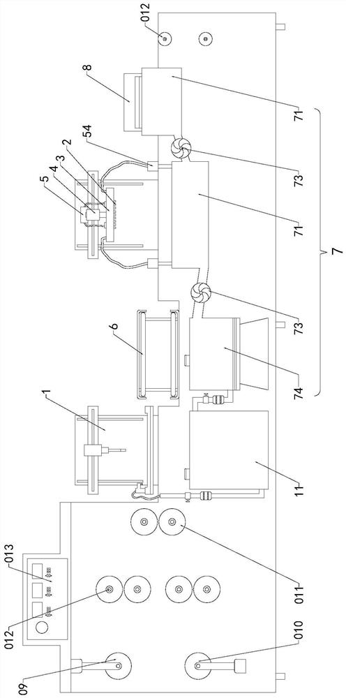
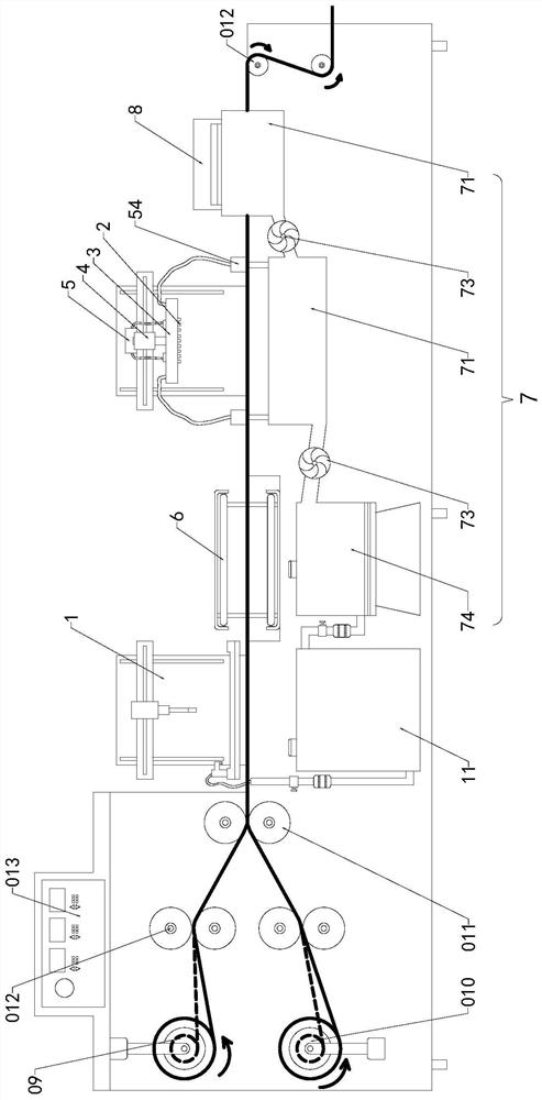
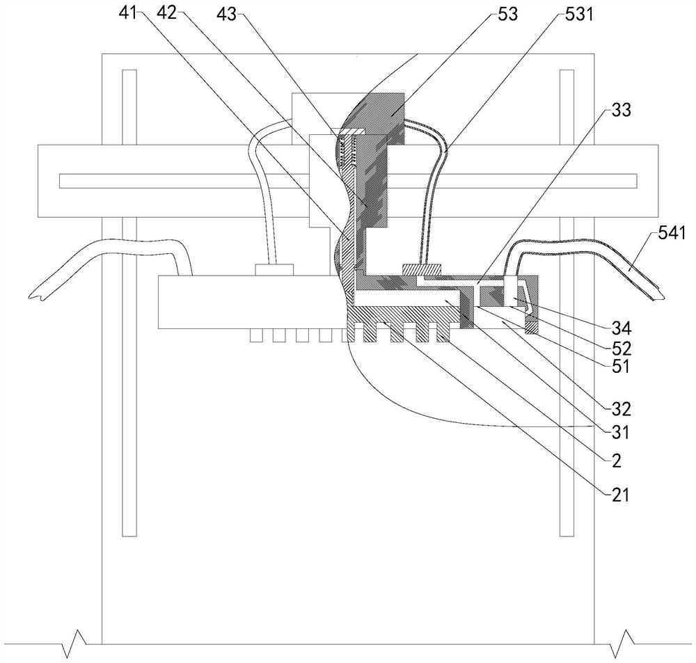
[0038] refer to Figure 1 to Figure 4 , figure 1 It is a schematic embodiment of a forming equipment for a graphene RFID electronic tag antenna. The electronic tag antenna is formed on the surface of a substrate by using graphene conductive paste as a raw material. It includes a printin...


PUM


Abstract

The invention discloses a forming device of a graphene RF ID electronic tag antenna. The forming device comprises a printing device, a gravure die, a die sleeve, an automatic compacting mechanism and a pneumatic material discharging mechanism. Firstly, an antenna with a first thickness is pre-printed on a base material through the printing device, wherein the first thickness is greater than a standard thickness; then a gravure die comprising a gravure groove with the shape and the groove depth corresponding to the shape and the thickness of the antenna is pressed to the base material, and the gravure groove is filled with the pre-printed antenna to complete shaping; in the shaping process, redundant slurry is extruded out of the gravure groove, and after the gravure die is attached to the surface of the base material, the redundant slurry is stripped and discharged through the pneumatic discharging mechanism; and then, the gravure die leaves the surface of the base material, and the graphene conductive slurry left on the base material forms the antenna with the standard shape and thickness. The automatic compacting mechanism comprises a movable part, a sliding sleeve and an elastic part, and matched connection and actions of the gravure die and the die sleeve are guaranteed. In this way, the antenna produced through the method has the shape, the thickness and the good density of a standard antenna at the same time.

Description

technical field [0001] The invention relates to the technical field of graphene, in particular to a forming device for a graphene RFID electronic tag antenna. Background technique [0002] RFID, also known as radio frequency identification technology, is a non-contact automatic data collection technology and one of the core technologies of the Internet of Things. At present, this technology has been widely used in almost all fields such as logistics warehousing, transportation, security and anti-counterfeiting, and mobile payment. A typical RFID system consists of readers, tags, and background software. RFID electronic tags are system data carriers that store object information and are consumables. With the popularization and application of Internet of Things technology in various fields, the demand for RFID electronic tags is blowing out. growth. RFID electronic tag antenna is a kind of communication induction antenna. At present, due to different materials and manufactur...

Claims


Application Information

Patent Timeline
IPC IPC(8): B41F9/00B41F9/06B41F23/04
CPCB41F9/00B41F9/063B41F9/06B41F23/04B41P2217/50
Inventor 刘振禹陈韶华马有明魏洪标刘进
Owner SHANDONG HUAGUAN SMART CARD
Learn More