Hollow prefabricated concrete pile and machining method thereof

A technology of prefabricated concrete and processing method, applied in the direction of manufacturing tools, sheet pile walls, infrastructure engineering, etc., can solve the problem of high construction cost, and achieve the effects of low equipment and electricity cost, weight reduction, and easy transportation and construction.

Inactive Publication Date: 2021-06-25
盐城中桩预制构件有限公司
View PDF5 Cites 0 Cited by
  • Summary
  • Abstract
  • Description
  • Claims
  • Application Information

AI Technical Summary

Problems solved by technology

Therefore, the corrosive geology prohibits the use of hollow square piles, resulting in higher construction costs

Method used


Image

  • Hollow prefabricated concrete pile and machining method thereof
  • Hollow prefabricated concrete pile and machining method thereof
  • Hollow prefabricated concrete pile and machining method thereof

Examples


Embodiment 1

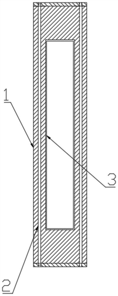
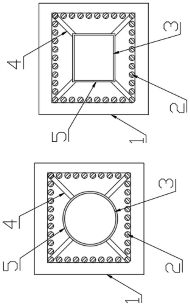
[0038] Such as figure 1 As shown, a hollow prefabricated concrete pile includes: a pile body 1, a main reinforcement 2, a core pipe 3, and a pile body 1. The pile body 1 is square or rectangular and formed by pouring precast concrete. There are multiple main reinforcements 2, which are located inside the pile body 1 and combined with the pile body 1. The main reinforcements 2 are bound into a reinforcement cage through spiral reinforcement. The distance between the main reinforcement 2 and the outer surface of the pile body 1 is 0-10mm farther than the existing standard. The main reinforcement 2 is provided with a pier head and is limited by an end plate. The core tube 3 is fixed to the center of the pile body 1 after being connected with the steel cage. The core tube 3 is a hollow round tube or square tube. The two ends of the core tube 3 are closed. the cavity,

[0039] The number of the core tube 3 is one or more, and when the section of the pile body 1 is square, a core ...

Embodiment 2

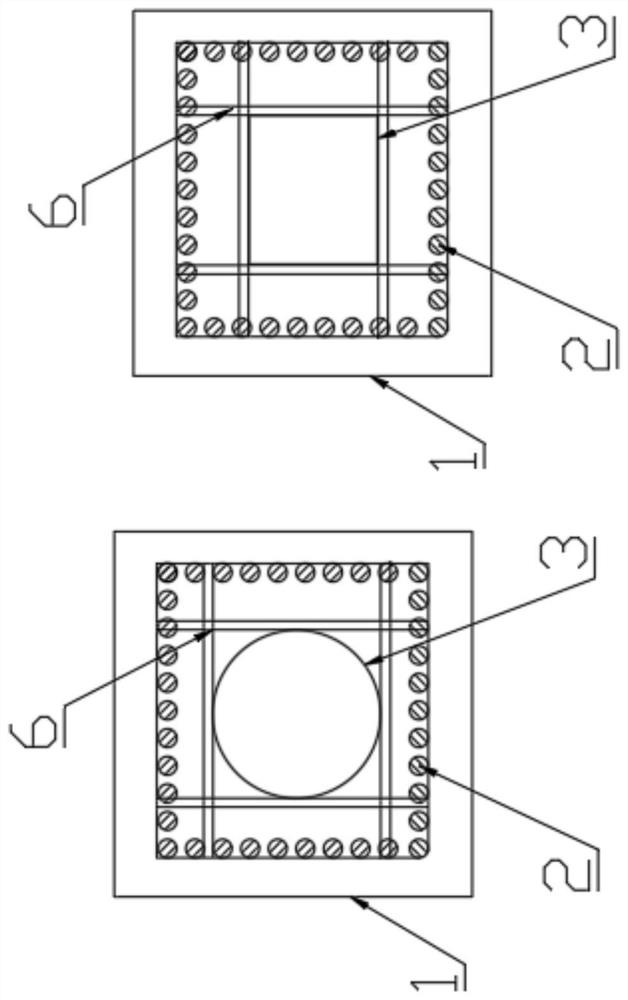
[0044] Other parts are identical with embodiment, except the fixing mode of core pipe 3 and reinforcement cage, as image 3 As shown, the core pipe 3 is fixed to the reinforcement cage through multiple sets of well-tac-toe supports 6 .

[0045] Correspondingly, a processing method of a hollow prefabricated concrete pile is disclosed, such as Figure 5 , 6 shown, including the following steps:

[0046] S1. To prepare concrete, mix cement, aggregate, water, admixtures, and admixtures in a certain proportion to form concrete.

[0047] S2. Fabrication of reinforcement cage. After the main reinforcement 2 is cut, pier head operation is performed. Multiple main reinforcement 2 are positioned through the end plate.

[0048] S3. Install the core tube 3. After the two ends of the core tube 3 are closed, insert the steel cage. The distance between the two ends of the core tube 3 and the two ends of the steel cage is the same. The distance between the side of the core tube 3 and each ...


PUM


Abstract

The invention relates to a hollow prefabricated concrete pile and a machining method thereof. The concrete pile comprises a pile body, a plurality of main ribs and a core pipe; the plurality of main ribs are arranged and bound into a reinforcement cage through spiral ribs; the distance between the main ribs and the outer surface of the pile body is 0-10mm larger than that of the existing standard; the main ribs are provided with pier heads and limited through end plates; the core pipe is connected with the reinforcement cage and then fixed to the center of the pile body; the core pipe is a hollow round pipe or a hollow square pipe; the two ends of the core pipe are closed; and the pile body is provided with a cavity with the section being round or square due to the core pipe. The machining method comprises the steps of concrete preparing, reinforcement cage manufacturing, core pipe installing, tensioning, pouring, steam curing and demolding. Compared with a hollow pile, the hollow prefabricated concrete pile can be used for corrosive geology, and the impact resistance of the end of the pile is improved during pile sinking; and compared with a solid pile, the usage amount of concrete is reduced, the weight of the concrete pile is reduced, cost is saved, transportation and construction are convenient, and meanwhile the difficulty of the manufacturing method is lowered.

Description

technical field [0001] The invention belongs to the field of concrete pile manufacture, and in particular relates to a hollow prefabricated concrete pile and a processing method thereof. Background technique [0002] Concrete piles have the advantages of saving wood and steel, durable, and low cost. They have been widely used in the foundation engineering of hydraulic construction, industrial construction, civil construction and bridges, and are also often used for anti-skid or isolation of slope and foundation pit support. water. [0003] At present, prefabricated concrete piles include hollow piles and solid piles. Compared with solid piles, the unit bearing capacity of hollow piles is lower. Due to its hollowness, shallow bearing layer and small diameter, the cost per unit bearing capacity is generally lower. Secondly, transportation, hoisting and pile sinking are convenient, and the construction speed is fast. However, for corrosive geology, the central hole of the ho...

Claims


Application Information

Patent Timeline
Patent Type & Authority Applications(China)
IPC IPC(8): E02D5/30B28B23/02
CPCE02D5/30B28B23/02
Inventor 李亚琴张云张孝平俞树宝
Owner 盐城中桩预制构件有限公司
Why Eureka
Try Eureka