High-airtightness passive house and construction process thereof

A construction technology and passive house technology, applied in the field of passive house, can solve the problems of insufficient utilization of exhausted gas, low resource utilization efficiency, and inability to allow fresh air to enter the room, and achieve strong air tightness, good thermal insulation effect, Safe and convenient to use

Active Publication Date: 2021-06-25
河北智博保温材料制造有限公司
View PDF5 Cites 2 Cited by
  • Summary
  • Abstract
  • Description
  • Claims
  • Application Information

AI Technical Summary

Problems solved by technology

[0004] The present invention provides a highly air-tight passive house and its construction technology, which can effectively solve the problem that the currently constructed passive house in the above-mentioned background technology cannot pass fresh air into the room during cooling and heating, and the exhausted gas Insufficient utilization leads to rapid heat loss during heating in passive houses, reduced air tightness, poor cooling effect during cooling, and low resource utilization efficiency

Method used


Image

  • High-airtightness passive house and construction process thereof
  • High-airtightness passive house and construction process thereof
  • High-airtightness passive house and construction process thereof

Examples


Embodiment

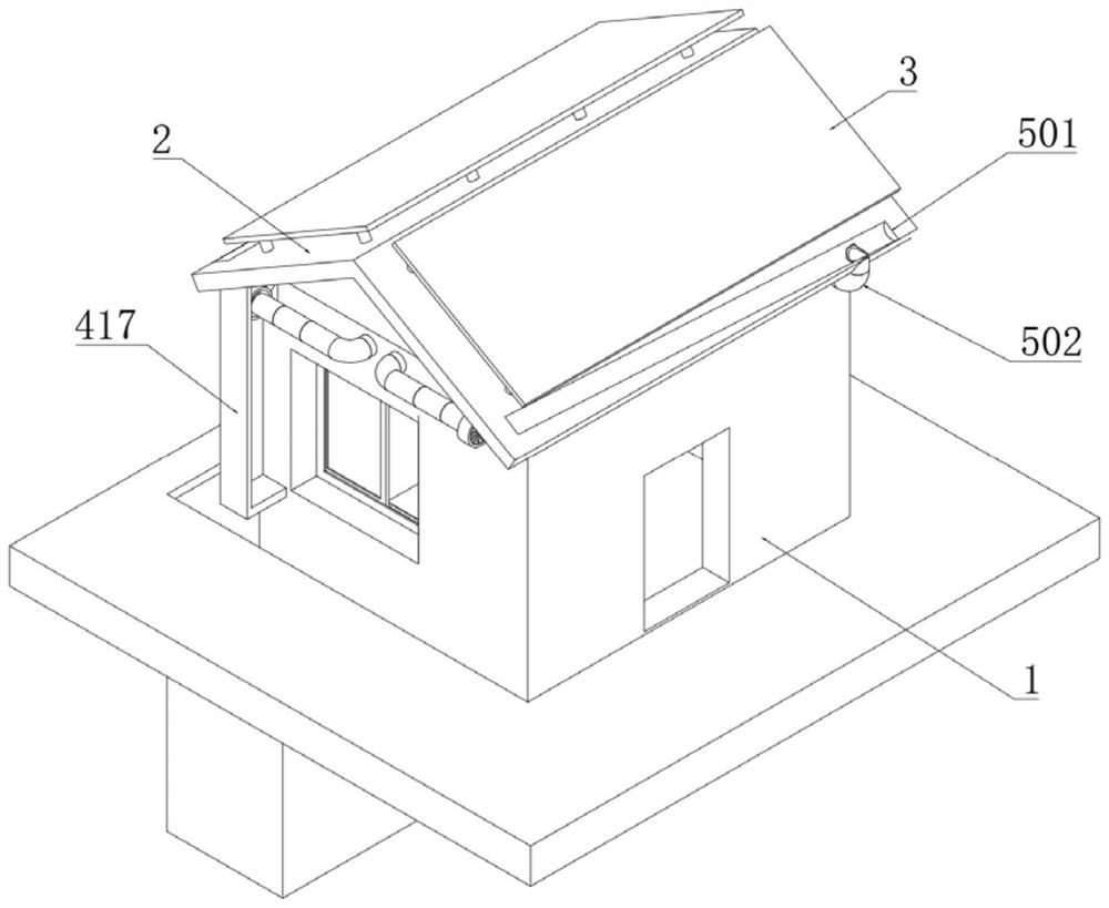
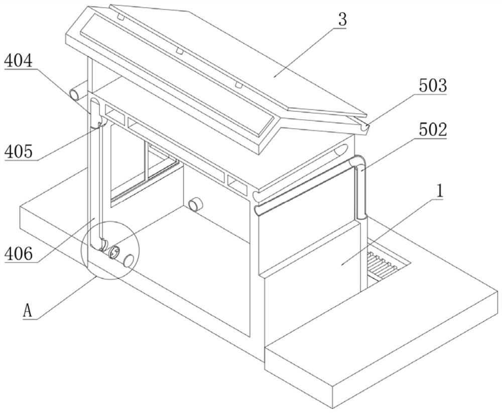
[0050] Example: such as Figure 1-8 As shown, the present invention provides a technical solution, a highly airtight passive house, comprising a wall 1, a roof 2 is installed on the top of the wall 1, a solar panel 3 is installed on the top of the roof 2, and the wall 1 Fresh air components are installed on the top;

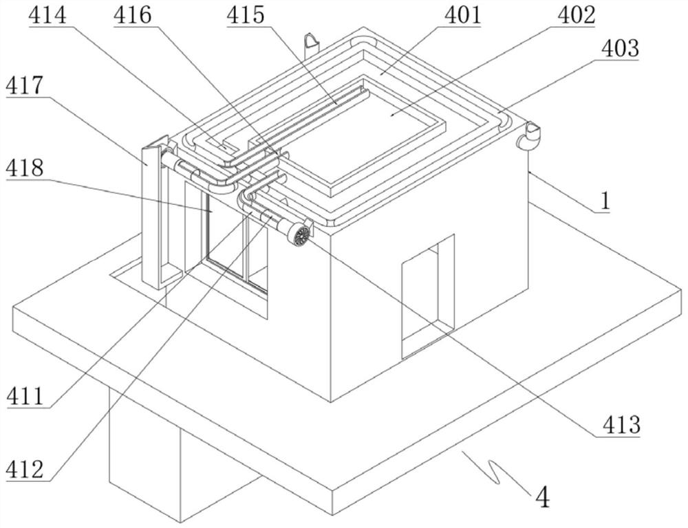
[0051] The fresh air assembly 4 includes a ventilation chamber 401, an inner air chamber 402, an outer air chamber 403, an air conveying groove 404, an upper air hole 405, an arc baffle 406, a lower air hole 407, a lifting block 408, a rotating ring 409, and a sealing cover 410 , air inlet pipe 411, fresh air filter element 412, blower fan 413, air inlet hole 414, connecting air pipe 415, exhaust pipe 416, exhaust baffle 417 and window 418;

[0052] There is a ventilation chamber 401 in the middle of the top of the wall 1, and an inner air chamber 402 is opened on the top of the wall 1 corresponding to the inside of the ventilation chamber 401, and the top of th...


PUM


Abstract

The invention discloses a high-airtightness passive house and a construction process thereof. The high-airtightness passive house comprises a wall body, wherein a roof is mounted at the top end of the wall body, a solar panel is mounted at the top end of the roof, a fresh air assembly is mounted at the top of the wall body, and an air exchange chamber is formed in the middle of the top of the wall body. According to the high-airtightness passive house, by arranging the air exchange chamber, an inner air cavity, an outer air cavity, an air conveying groove, an upper air hole, an arc-shaped baffle, a lower air hole, an air inlet pipe and an air inlet hole, the lower air hole is opened, and air enters the air conveying groove, the outer air cavity, a connecting air pipe and the inner air cavity from the lower air hole; and finally 2, by arranging the connecting air pipe, an exhaust pipe and an exhaust baffle, cold air in the air exchange chamber is preheated through waste heat of hot air passing through the inner air cavity and the outer air cavity, the preheated air enters a room through the air inlet hole, the temperature difference between outdoor air and indoor air is reduced, fresh air can enter the room during refrigerating and heating, thus the indoor air is fresher, and the environment is more comfortable.

Description

technical field [0001] The invention relates to the technical field of passive houses, in particular to a highly airtight passive house and its construction technology. Background technique [0002] The passive house is a master of various technical products. By making full use of renewable energy, the sum of all the primary energy consumed does not exceed 120 kW·h / (square meter. year). Such a low energy consumption standard is achieved through high Heat insulation and sound insulation, strong airtight building exterior walls and renewable energy can be realized. "Passive house" is a new energy-saving building concept advocated abroad, and it is also an important opportunity and platform for my country to promote building energy conservation; [0003] However, the currently constructed passive houses cannot allow the fresh air to enter the room well during cooling and heating, and do not make full use of the exhausted gases, resulting in rapid heat loss when the passive house...

Claims


Application Information

Patent Timeline
Patent Type & Authority Applications(China)
IPC IPC(8): E04B1/00E04B1/66E04B1/76E04B2/00E04D13/18E04D13/04E04D13/08E03B3/02E03F5/10E03B1/04F24S25/61F24F7/06F24F7/003F24F13/28F24F13/02G01M3/02H02S20/23
CPCE04B1/00E04B1/66E04B1/76E04B2/00E04D13/00E04D13/04E04D13/08E03B3/02E03F5/10E03B1/04E03B1/041F24S25/61F24F7/06F24F13/28F24F13/02G01M3/02H02S20/23E03B2001/047Y02A20/108Y02E10/47Y02E10/50Y02B10/20Y02B10/10
Inventor 赵猛祁帮增
Owner 河北智博保温材料制造有限公司
Why Eureka
Try Eureka