A dual-rotor internal combustion engine

An internal combustion engine, double rotor technology, applied in the direction of internal combustion piston engine, combustion engine, mechanical equipment, etc., can solve the problems of difficult sealing treatment, poor workmanship of crankshaft of multi-cylinder internal combustion engine, limited volume of piston internal combustion engine, etc. High conversion efficiency and the effect of increasing power

Active Publication Date: 2022-04-19
杨文通
View PDF8 Cites 2 Cited by
  • Summary
  • Abstract
  • Description
  • Claims
  • Application Information

AI Technical Summary

Problems solved by technology

However, the piston internal combustion engine also has disadvantages
First, the structure of the piston internal combustion engine is loose, and the camshaft of the intake and exhaust control mechanism is far away from the main shaft; second, the crankshaft of the multi-cylinder internal combustion engine is poor in workmanship; third, the volume of each cylinder of the piston internal combustion engine is limited, so it is necessary to obtain greater output power More cylinders are often required; finally, the piston internal combustion engine is most criticized for its useless reciprocating motion
[0003] The triangular rotor engine and the Quasi engine are rare internal combustion engines that do not rely on reciprocating motion to change the volume of the combustion chamber. However, this type of internal combustion engine has a line contact between the rotor and the cylinder, which is difficult to seal, so it has not been widely used.
In addition, there is currently no effective mechanism movement method that can replace the reciprocating movement of the piston to change the volume of the combustion chamber of the internal combustion engine.

Method used


Image

  • A dual-rotor internal combustion engine
  • A dual-rotor internal combustion engine
  • A dual-rotor internal combustion engine

Examples


Embodiment 1

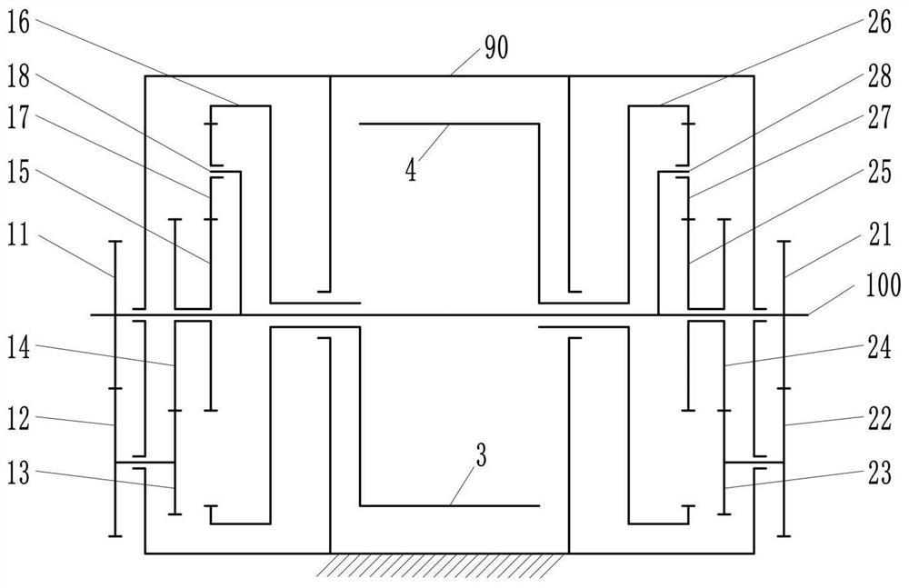
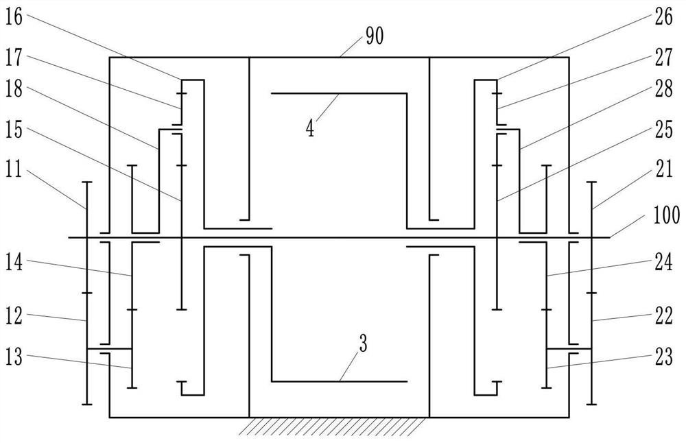
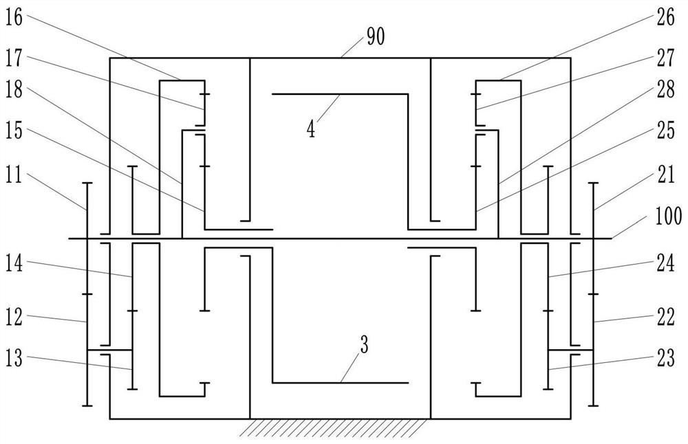
[0144] refer to Figure 1 to Figure 15 , the dual rotor internal combustion engine that embodiment 1 provides comprises:

[0145] Left short shaft 10, left first gear 11, left second gear 12, left third gear 13, left fourth gear 14, left fifth gear 15, left sixth gear 16, three left planetary wheels 17, left planetary frame 18;

[0146] Right short shaft 20, right first gear 21, right second gear 22, right third gear 23, right fourth gear 24, right fifth gear 25, right sixth gear 26, three right planetary wheels 27, right planetary Rack 28;

[0147] Left support body 30, left blade 31, left counterweight 35;

[0148] Right support body 40, right blade 41, right counterweight 45;

[0149] Left sealing plate 50, left supporting cover 51, left sealing cover 52;

[0150] Right sealing plate 60, right supporting cover 61, right sealing cover 62;

[0151] Left cam 70, left air channel 71, left valve 72, left ejector rod 73, left spring 74;

[0152] Right cam 80, right air cha...

Embodiment 2

[0208] Embodiment 2 is a derivative solution of Embodiment 1. All the parts contained in Embodiment 1 can find their corresponding parts in Embodiment 2, and the connection relationship of these parts remains unchanged. The twin rotor internal combustion engine that embodiment 2 provides, its concrete structure is as Figures 21 to 23shown. Wherein, the position and connection relationship of the first gear, the second gear, the planetary gear, the first bearing, the second bearing, the sixth bearing, and the seventh bearing that are not shown can refer to the parts with the same name in the first embodiment.

[0209] Compared with embodiment 1, the components of embodiment 2 have more second spark plug 93, second fuel injector 94; left second cam 75, left second air channel 76, left second valve 77, left second top Rod 78, left second spring 79; Right second cam 85, right second air passage 86, right second air valve 87, right second push rod 88, right second spring 89. Sim...

Embodiment 3

[0213] refer to Figure 24 to Figure 30 , the dual-rotor internal combustion engine provided in Embodiment 3 includes:

[0214] Left short shaft 10, left first gear 11, left second gear 12, left third gear 13, left fourth gear 14, left fifth gear 15, left sixth gear 16, three left planetary wheels 17, left planetary Frame 18, left pad 19;

[0215] Right short shaft 20, right first gear 21, right second gear 22, right third gear 23, right fourth gear 24, right fifth gear 25, right sixth gear 26, three right planetary wheels 27, right planetary Frame 28, right block 29;

[0216] Left support body 30, left first blade 31, left second blade 32;

[0217] Right support body 40, right first blade 41, right second blade 42;

[0218] Left sealing plate 50, left supporting cover 51, left sealing cover 52;

[0219] Right sealing plate 60, right supporting cover 61, right sealing cover 62;

[0220] Left cam 70, left first air passage 71, left first air valve 72, left first push rod ...


PUM


Abstract

The invention discloses a double-rotor internal combustion engine, which comprises a cylinder, a main shaft, left and right rotors, and a left and right intermittent motion mechanism. The cylinder includes an axially penetrating cylinder hole, the rotor includes blades and a support body, and the intermittent motion mechanism is a closed differential gear train including a non-circular gear pair, which can realize continuous and smooth shifting. The left rotor, right rotor and main shaft are located inside the cylinder and have coaxial rotation degrees of freedom. The blades of the two left and right rotors are radially juxtaposed, and the space between the blades constitutes a combustion chamber. The two rotors rotate periodically and intermittently during the ignition, power, exhaust, suction, and compression processes of the internal combustion engine, and the left rotor moves When the right rotor is stationary, the left rotor is stationary when the right rotor is moving. The left and right rotors transmit their respective intermittent rotations to the main shaft through the left and right intermittent motion mechanisms, and convert them into constant rotational speeds. Under the action of inertia, the main shaft feeds back its own rotation to the left and right rotors to control its acceleration, deceleration and static process.

Description

technical field [0001] The invention relates to the field of internal combustion engines, in particular to a double-rotor internal combustion engine. Background technique [0002] In addition to gas turbines, internal combustion engines generally drive pistons through intake, compression, explosion, and exhaust processes, and piston internal combustion engines are the most typical representatives. The piston internal combustion engine is widely used because of its simple principle, reliable operation and good air tightness. However, piston internal combustion engines also have disadvantages. First, the structure of the piston internal combustion engine is loose, and the camshaft of the intake and exhaust control mechanism is far away from the main shaft; second, the crankshaft of the multi-cylinder internal combustion engine is poor in workmanship; third, the volume of each cylinder of the piston internal combustion engine is limited, and it is necessary to obtain greater o...

Claims


Application Information

Patent Timeline
Patent Type & Authority Patents(China)
IPC IPC(8): F02B53/00F02B53/14F02B55/02F02B55/08F02B55/16F16H48/06
CPCF02B53/00F02B53/14F02B55/02F02B55/16F02B55/08F16H48/06Y02T10/12
Inventor 杨文通
Owner 杨文通
Why Eureka
Try Eureka