Fault monitoring method for reciprocating equipment

A fault monitoring, reciprocating technology, applied in the direction of mechanical equipment, pump testing, measuring devices, etc., can solve the problems of difficult to determine the corresponding relationship between frequency bands and faulty components, lack of effective training samples, low degree of automation, etc., and achieve significant monitoring sensitivity , to ensure accuracy, and to monitor the effects of increased sensitivity

Active Publication Date: 2021-06-25
苏州德姆斯信息技术有限公司
View PDF2 Cites 2 Cited by
  • Summary
  • Abstract
  • Description
  • Claims
  • Application Information

AI Technical Summary

Problems solved by technology

However, in the current implementation process, manual analysis is needed to complete the fault diagnosis, which has high technical and experience requirements for analysts, which not only has a low degree of automation but also consumes a lot of human resources.
For this reason, some scholars proposed to monitor the vibration amplitude of the pump in different frequency bands to correspond to the faults of some parts of the equipment. However, due to the large number of components in the equipment, the excitation force and natural frequency of different equipment are different. Therefore, the correspondence between the frequency band and the faulty part is difficult to determine
In addition, some researchers have proposed to use deep neural network or other machine learning methods to train a fault diagnosis model of reciprocating equipment, but this method lacks effective training samples under different working conditions and different fault types, and is limited Due to the influence of sample sampling frequency, the trained model has poor versatility and cannot be used in actual industrial situations

Method used


Image

  • Fault monitoring method for reciprocating equipment
  • Fault monitoring method for reciprocating equipment
  • Fault monitoring method for reciprocating equipment

Examples


Embodiment Construction

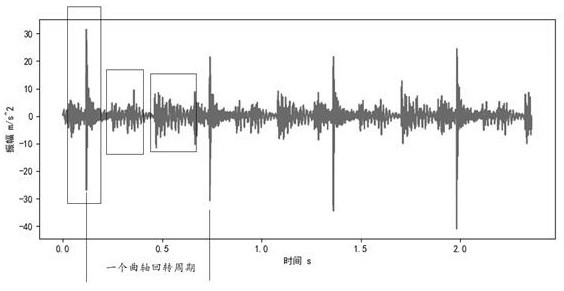
[0044] The invention discloses a fault monitoring method for reciprocating equipment, focusing on the vibration signal during the operation of the equipment, taking the reciprocating equipment as a three-cylinder mud pump as an example, which drives the drive through the crankcase (crankshaft connecting rod structure) The rotary motion of the machine part is converted into the reciprocating motion of the output system part. When the piston in the output system moves to the limit position every time, a vibration shock will be generated. Specifically, the vibration signal diagram of a cylinder head of a three-cylinder mud pump is as follows figure 1 shown.

[0045] From figure 1 It can be known that in one crankshaft revolution cycle of the crankcase part, when the piston in the cylinder closest to the sensor moves to the stop position, a vibration shock appears on the vibration signal; and when the other two distances are slightly When the pistons in the far cylinders also arri...


PUM


Abstract

The invention discloses a fault monitoring method for reciprocating equipment. The method comprises the following steps of S1, collecting a plurality of vibration acceleration signals, selecting one vibration acceleration signal, intercepting a segment of the vibration acceleration signal as a reference signal, and taking the rest as a training data set; S2, selecting a plurality of signal segments from the signals in the training data set, calculating a cross correlation coefficient between each signal segment and the reference signal, taking the signal segment corresponding to the maximum result as a training sample, traversing the training data set and summarizing the reference signals to obtain a training sample; S3, converting the training sample to obtain an upper envelope line and a lower envelope line; S4, collecting a vibration acceleration signal to be monitored, and obtaining a detection sample; and S5, comparing whether the detection sample exceeds the upper envelope line and the lower envelope line, if not, marking as normal, and if yes, marking as abnormal, and giving an alarm. According to the method, the monitoring of the vibration signal is realized in a full-automatic manner, the dependence of the method on human resources is reduced, and the accuracy of the monitoring effect is ensured.

Description

technical field [0001] The invention relates to a fault monitoring method, in particular to a fault monitoring method of reciprocating equipment, and belongs to the field of mechanical equipment fault diagnosis. Background technique [0002] Since the 1960s, in order to meet the development needs of aviation, military industry, and industrial production, the discipline of mechanical fault diagnosis has begun to rise. A lot of research results have been obtained on the state detection and fault diagnosis of rotating equipment (such as bearings, gears, etc.). Different from rotary equipment, reciprocating equipment has a more complicated internal structure, many moving parts, and many exciting parts. The probability of failure and the difficulty of fault monitoring are much higher than that of rotary equipment. Therefore, the maintenance of reciprocating equipment is still Regular maintenance and after-the-fact repairs are carried out, and there is no truly effective fault mo...

Claims


Application Information

Patent Timeline
Patent Type & Authority Applications(China)
IPC IPC(8): F04B51/00G01H17/00G01P15/00G06K9/62G06K9/00
CPCF04B51/00G01H17/00G01P15/00G06F2218/00G06F18/214
Inventor 邓刚张玉斌程攀勇
Owner 苏州德姆斯信息技术有限公司
Why Eureka
Try Eureka