Shafting structure of self-lubricating turbocharger ball bearing

A turbocharger and self-lubricating technology, applied in the field of shafting lubrication, can solve problems such as bearing scratches, affecting the safe use of the engine, sintering or sealing system failure, etc., to solve the bearing radial and axial load, shafting Structural operation is stable and reliable, and the effect of excellent heat dissipation

Pending Publication Date: 2021-06-25
HUNAN TYEN MACHINERY
View PDF0 Cites 1 Cited by
  • Summary
  • Abstract
  • Description
  • Claims
  • Application Information

AI Technical Summary

Problems solved by technology

[0004] As the turbocharger uses engine lubricating oil, the aging of the engine lubricating oil will contain piston wear metal particles, engine micro-particle carbon residue, corrosion on the inner wall of the lubricating oil pipeline, etc., which will cause scratches on the turbocharger bearings, abnormal wear, and bearing sticking , sintering or sealing system failure, eventually causing a large amount of turbocharger lubricating oil to leak out, seriously affecting the safe use of the engine

Method used


Image

  • Shafting structure of self-lubricating turbocharger ball bearing

Examples


Embodiment 1

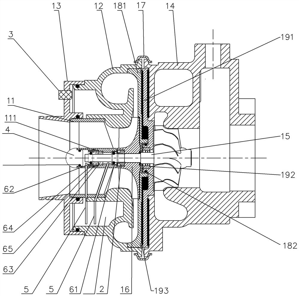
[0021] Such as figure 1 The shown turbocharger with self-lubricating ball bearing shafting structure includes bearing housing 11, compressor volute 12, oil seal cover 13, turbine case 14, rotor shaft 15, impeller 16 and back plate assembly, compressor The volute 12 and the turbine case 14 are connected as a whole by a clamp 17, the outer circumference of the bearing housing 11 is riveted (or inlaid) on the air inlet of the compressor volute 12, and the oil sealing cap 13 is set on the outer circumference of the end of the bearing housing 11. An oil storage chamber 2 is formed between the oil seal cover 13, the bearing seat 11 and the compressor volute 12, wherein the contact surface between the oil seal cover 13 and the compressor volute 12, and the contact surface between the oil seal cover 13 and the bearing seat 11 O-shaped sealing rings are installed at all places to ensure the sealing effect of the oil storage chamber 2. The oil sealing cover 13 is provided with a ventila...


PUM


Abstract

The invention relates to the technical field of shafting lubrication, and discloses a shafting structure of a self-lubricating turbocharger ball bearing. A turbocharger comprises a bearing seat, a gas compressor volute, an oil sealing cover, a turbine box, a rotor shaft, an impeller and a back disc assembly. The back disc assembly comprises a back disc cooperating with the gas compressor volute, the turbine box is connected with the gas compressor volute, the periphery of the bearing seat is embedded into a gas inlet of the gas compressor volute, an oil storage cavity is formed among the oil sealing cover, the bearing seat and the gas compressor volute, and the pressure in the oil storage cavity and the environmental pressure are balanced. The shafting structure comprises a sleeve part arranged at the position of a center shaft of the bearing seat, the rotor shaft and the impeller are assembled and inserted into the sleeve part, a bearing seat cavity is formed among the rotor shaft, the impeller and the inner wall of the sleeve part, a bearing assembly is arranged on the shaft section, inserted into the sleeve part, of the rotor shaft, and a channel capable of conveying lubricating oil is arranged between the bearing seat cavity and the oil storage cavity. The oil storage cavity and the channel are arranged, and the micro-negative pressure environment of the bearing seat cavity is utilized to ensure that lubricating oil is automatically conveyed along the channel to lubricate the shafting structure.

Description

technical field [0001] The invention belongs to the technical field of shafting lubrication, and in particular relates to a shafting structure of a self-lubricating turbocharger ball bearing. Background technique [0002] At present, the bearing lubrication system of turbocharged technology products at home and abroad basically adopts external oil supply lubrication technology, and turbocharger shaft systems such as double floating bearings, semi-floating bearings and ball bearings use engine lubrication to lubricate and dissipate heat from their shaft bearings. The lubricating oil inlet of the turbocharger is connected with the main oil passage of the engine to form an oil inlet pipeline; the lubricating oil return of the turbocharger is connected with the engine oil pan to form an oil return pipeline. The oil inlet and return pipes of the turbocharger are special parts, and the engine needs to be specially designed to require sealing, high pressure resistance, corrosion re...

Claims


Application Information

Patent Timeline
Patent Type & Authority Applications(China)
IPC IPC(8): F04D25/04F04D29/05F04D29/056F04D29/059F04D29/063F02B37/00F02B39/14
CPCF04D25/045F04D29/05F04D29/0563F04D29/059F04D29/063F02B37/00F02B39/14Y02T10/12
Inventor 周峥封金虎闫海东曹刚胡奇凌泓王星周贵平许洪
Owner HUNAN TYEN MACHINERY
Why Eureka
Try Eureka