
Device and method for demodulating optical fiber interferometric sensor with vernier effect based on silicon-based microring

A vernier effect and optical fiber interference technology, which is applied in the direction of converting sensor output, using optical devices to transmit sensing components, measuring devices, etc., can solve the problems of bulky, high cost, and difficulty in realizing large-scale physical parameter sensing. The effect of large measurement range and improved demodulation sensitivity

Active Publication Date: 2022-07-01
NORTHWEST UNIV
View PDF17 Cites 0 Cited by
  • Summary
  • Abstract
  • Description
  • Claims
  • Application Information

AI Technical Summary

Problems solved by technology

If the spectrum drifts through a whole matching period, it cannot be distinguished, and it is difficult to realize the sensing of a wide range of physical parameters
Therefore, although the measurement accuracy is improved, the measurement range is limited
In addition, the vernier effect demodulation methods reported at present all use large-scale equipment such as spectrometers, which are expensive and bulky, and are not suitable for outdoor testing.

Method used


Image

  • Device and method for demodulating optical fiber interferometric sensor with vernier effect based on silicon-based microring
  • Device and method for demodulating optical fiber interferometric sensor with vernier effect based on silicon-based microring
  • Device and method for demodulating optical fiber interferometric sensor with vernier effect based on silicon-based microring

Examples


Embodiment 1

[0025] In this embodiment, the present invention is described by taking the demodulation of the optical fiber Fabry-Perot interferometer 3 as an example.

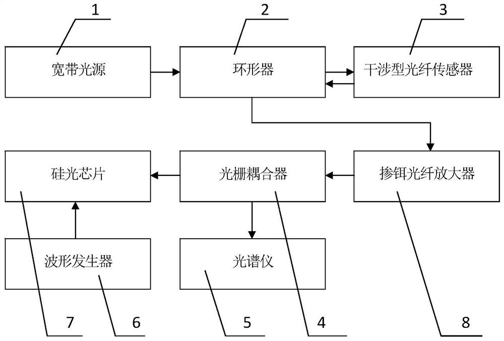
[0026] exist figure 1 Among them, the demodulation device of the vernier effect optical fiber interferometric sensor based on silicon-based microring in this embodiment consists of a broadband light source 1, a circulator 2, a fiber Fabry-Perot interferometer 3, a grating coupler 4, a spectrometer 5, and a waveform generator. 6. The silicon photonic chip 7 and the erbium-doped fiber amplifier 8 are connected to form. The laser light emitted from the broadband light source 1 enters the circulator 2 through the optical fiber. The circulator 2 is connected to the fiber Fabry-Perot interferometer 3 and the input end of the fiber amplifier through the fiber. The output end of the fiber amplifier is connected to the silicon optical chip through the grating coupler 4. 7 is connected, the silicon photonic chip 7 is connected with ...


PUM

PropertyMeasurementUnit
widthaaaaaaaaaa
thicknessaaaaaaaaaa
radiusaaaaaaaaaa

Abstract

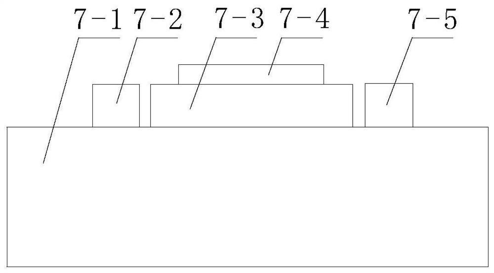
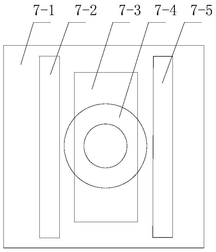
A device and method for demodulating a vernier effect optical fiber interference sensor based on a silicon-based microring. Laser light emitted from a broadband light source enters a circulator through an optical fiber, and the circulator is connected to an input end of an interference type optical fiber sensor and an optical fiber amplifier through an optical fiber. The output end is connected to the silicon optical chip through a grating coupler, and the silicon optical chip is an SOI substrate provided with a first straight waveguide and a second straight waveguide with the same structure, and between the first straight waveguide and the second straight waveguide The annular waveguide has a gap between the annular waveguide, the first straight waveguide and the second straight waveguide, and a heating electrode is arranged on the annular waveguide. The invention uses the silicon optical chip to demodulate the optical fiber interference sensor, so that the demodulation device is miniaturized. The optical signal reflected by the optical fiber interference sensor enters the silicon optical chip and the spectrum of the silicon optical chip is superimposed to produce a vernier effect, thereby improving the demodulation sensitivity and increasing the the measurement range.

Description

technical field [0001] The invention belongs to the technical field of optical fiber demodulation, and in particular relates to a device and method for demodulating a vernier effect optical fiber interference sensor based on a silicon-based microring. Background technique [0002] Optical fiber sensors are widely used in the measurement of external physical quantities such as temperature, refractive index, pressure, and strain due to their simple structure, small size, light weight, anti-electromagnetic interference and high sensitivity. Among them, optical fiber temperature and strain sensors have been widely studied in the past two decades, and have broad application prospects in aerospace, industrial production, safety monitoring and other fields. [0003] Common fiber temperature and strain sensors are generally based on fiber grating or fiber interferometer structures. The sensitivity of temperature and strain sensors based on fiber grating structures is usually low, ge...

Claims


Application Information

Patent Timeline
Patent Type & Authority Patents(China)
IPC IPC(8): G01D5/353
CPCG01D5/35306G01D5/35329G01D5/35322G01D5/35312G01D5/35377
Inventor 王若晖李敏轩乔学光
Owner NORTHWEST UNIV
Learn More