Crop root zone multi-frequency electrical impedance imaging method and system

An electrical impedance imaging and electrical impedance technology, applied in material resistance, medical science, sensors, etc., can solve the problems of large error and slow imaging speed, and achieve the effect of optimizing imaging effect, improving crop yield, and monitoring root health status in real time.

Pending Publication Date: 2021-06-29
CHINA AGRI UNIV
View PDF6 Cites 1 Cited by
  • Summary
  • Abstract
  • Description
  • Claims
  • Application Information

AI Technical Summary

Problems solved by technology

[0004] Since the single-frequency electrical impedance imaging technology only uses a fixed frequency as the excitation frequency, the electrical impedance imaging can only obtain the electrical impedance distribution at one frequency at a time, and the state of the organism will also change during a long measurement time , resulting in a larger error
Multi-frequency electrical impedance imaging technology can quickly obtain the electrical impedance distribution at multiple frequencies, but the existing multi-frequency electrical impedance imaging technology scans serially frequency by frequency, and the imaging speed is slow

Method used


Image

  • Crop root zone multi-frequency electrical impedance imaging method and system
  • Crop root zone multi-frequency electrical impedance imaging method and system
  • Crop root zone multi-frequency electrical impedance imaging method and system

Examples


Embodiment Construction

[0045] In order to make the purpose, technical solutions and advantages of the embodiments of the present invention clearer, the technical solutions in the embodiments of the present invention will be clearly and completely described below in conjunction with the drawings in the embodiments of the present invention. Obviously, the described embodiments It is a part of embodiments of the present invention, but not all embodiments. Based on the embodiments of the present invention, all other embodiments obtained by persons of ordinary skill in the art without creative efforts fall within the protection scope of the present invention.

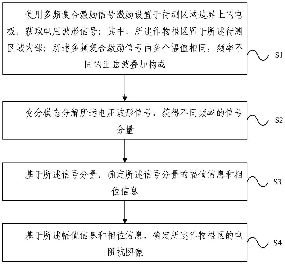
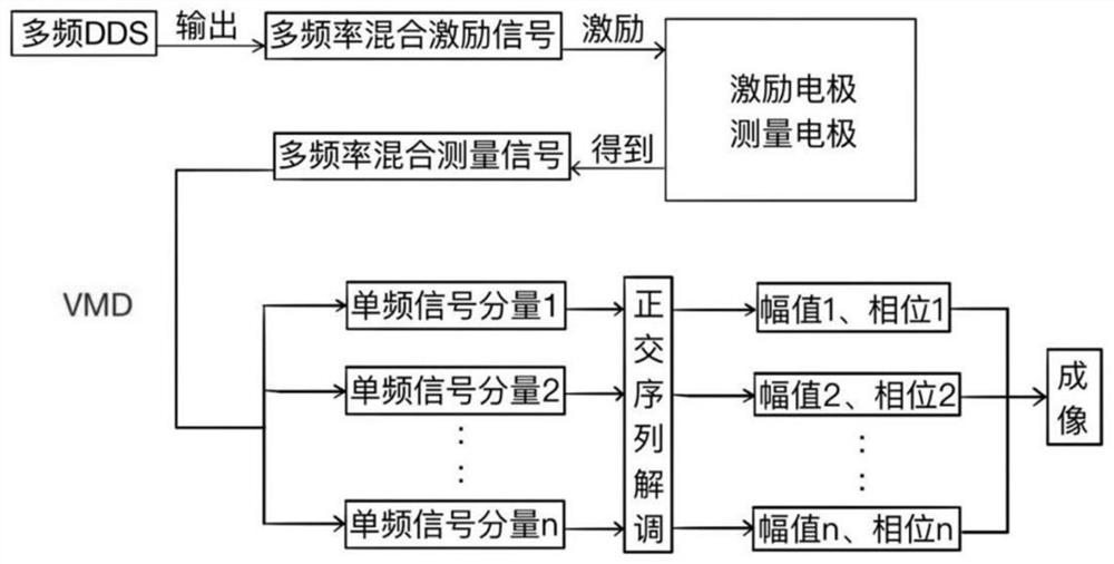
[0046] figure 1 The flow chart of multi-frequency electrical impedance imaging method for crop root zone provided by the present invention, such as figure 1 As shown, the present invention provides a kind of multi-frequency electrical impedance imaging method of crop root zone, comprising:

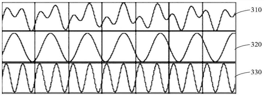
[0047] Step S1, using a multi-frequency composite exci...


PUM


Abstract

The invention provides a crop root zone multi-frequency electrical impedance imaging method and system. The crop root zone multi-frequency electrical impedance imaging method comprises the following steps of: using a multi-frequency compound excitation signal to excite an electrode arranged on the boundary of a zone to be tested, and obtaining a voltage waveform signal, wherein a crop root zone is arranged in the zone to be tested, and the multi-frequency compound excitation signal is formed by overlaying a plurality of sine waves with the same amplitude value and different frequencies; carrying out variation mode decomposition on the voltage waveform signal to obtain signal components of different frequencies; on the basis of the signal components, determining the amplitude value information and the phase information of the signal component; and on the basis of the amplitude value information and the phase information, determining an electrical impedance image of the crop root zone. By use of the crop root zone multi-frequency electrical impedance imaging method, the overlapped multi-frequency signals can be used as the excitation signal in parallel to carry out scanning, a single-frequency signal can be quickly separated from the multi-frequency signals, and correct imaging is carried out on the basis of guaranteeing accurate amplitude and phase and a high signal to noise ratio.

Description

technical field [0001] The invention relates to the technical field of agricultural production, in particular to a multi-frequency electrical impedance imaging method and system for crop root zones. Background technique [0002] The root zone of plants is often the "hidden" part of the plant, but it is very functional, traditionally its main function being the uptake of water and nutrients. The entire root zone of a plant includes the root system of the plant and the soil, which in turn provides the necessary water and nutrients for the growth of the root system. The root system of crops is an important organ to maintain the healthy growth of crops, and its growth, death, and disease have a great impact on crop yield. Therefore, the root zone is an important part of the study to improve crop yield, especially to improve the yield of crops grown in dry areas. [0003] Electrical Impedance Tomography (EIT) technology is a non-invasive, fast, low-cost, safe, and simple system...

Claims


Application Information

Patent Timeline
Patent Type & Authority Applications(China)
IPC IPC(8): A61B5/0536G01N27/04
CPCA61B5/0536G01N27/04
Inventor 王忠义潘庆欣黄岚李洋王楠赵鹏飞
Owner CHINA AGRI UNIV
Why Eureka
Try Eureka