
Charging unit for quick-change battery of electric vehicle, electric vehicle battery changing station and energy storage station

A technology for electric vehicles and charging units, applied in electric vehicle charging technology, electric vehicles, charging stations, etc., can solve the problems of easy electromagnetic interference between control lines, easy accumulation of heat in wiring, and complicated wiring, so as to reduce long-distance power transmission. Need, avoid electromagnetic interference, increase the effect of heat dissipation area

Pending Publication Date: 2021-06-29
AULTON NEW ENERGY AUTOMOTIVE TECHNOLOGY GROUP
View PDF6 Cites 0 Cited by
  • Summary
  • Abstract
  • Description
  • Claims
  • Application Information

AI Technical Summary

Problems solved by technology

[0006] The technical problem to be solved by the present invention is to overcome the disadvantages of complex wiring, high cost and difficulty, easy accumulation of heat in wiring, and easy electromagnetic interference between control lines in the existing technology, and provide a low-cost, Simple, easy to damage the wiring, and the electromagnetic interference between the lines is not easy to charge the charging unit of the electric vehicle quick-change battery, the electric vehicle replacement station and the energy storage station

Method used


Image

  • Charging unit for quick-change battery of electric vehicle, electric vehicle battery changing station and energy storage station
  • Charging unit for quick-change battery of electric vehicle, electric vehicle battery changing station and energy storage station
  • Charging unit for quick-change battery of electric vehicle, electric vehicle battery changing station and energy storage station

Examples


Embodiment 1

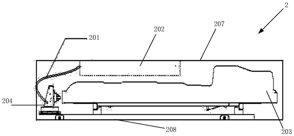
[0037] The invention provides a charging unit of an electric vehicle changing station, which is used to charge a quick-change battery of an electric vehicle, such as figure 2 As shown, the charging unit 2 forms a charging space, including a charger 202 and an electrical connection base 204 located in the charging space. The charger 202 includes a DC output interface, and the DC output interface is electrically connected to the electrical connection base 204; the electrical connection base 204 It includes a high-voltage pole for realizing electrical connection with the quick-change battery 203 .

[0038] Wherein, when the fast charging battery 203 is inserted on the electrical connection base 204, fast charging can be realized through the high-voltage pole, 201 represents a DC wire, and the DC output interface of the charger 202 is connected to the DC input of the electrical connection base 204 through the DC wire 201. Interface connection, so that the charger 202 can provide ...

Embodiment 2

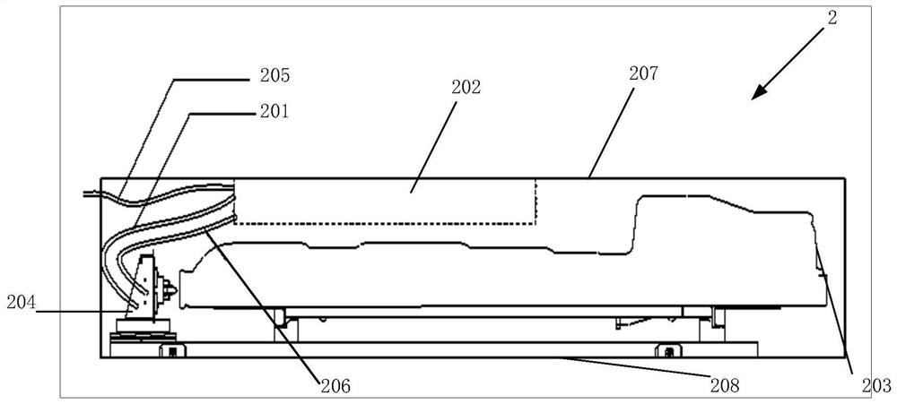
[0042] This embodiment is a further improvement on the basis of embodiment 1, such as image 3As shown, the charger 202 also includes a first communication interface, and the first communication interface communicates with the electrical connection base 204 through the communication cable 206. communication connection.

[0043] Wherein, in the charging unit 2 in the present embodiment, the charger 202 includes an AC input interface for external AC power supply, wherein the AC power supply is connected to the charger 202 through the AC wire 205, and the external AC power supply is connected to the battery 203 through the AC wire 205. The charger 202 supplies power.

[0044] It should be understood that, in the charging unit 2 , the charger 202 and the electrical connection base 204 are directly connected through the charging DC wire 201 , and each charging unit 2 provides an AC input interface externally, and receives AC power through the AC wire 205 .

[0045] Wherein, the c...

Embodiment 3

[0051] This embodiment provides an electric vehicle power station, Figure 4 A schematic diagram of some modules of the electric vehicle swapping station in this embodiment is shown. Such as Figure 4 As shown, the electric vehicle swapping station in this embodiment includes several charging units 2 in Embodiment 2.

[0052] Wherein, the electric vehicle replacement station includes a charging stand 30 , and the charging units 2 are arranged in a matrix on the charging stand 30 .

[0053] Wherein, the charging rack 30 includes a plurality of horizontal frames and vertical frames arranged at intervals, and the horizontal frames constitute the upper and lower racks of the battery holder in the charging space. The horizontal frame, for the upper charging unit, the horizontal frame is the lower frame, and for the lower charging unit, the horizontal frame is the upper frame. Figure 4 It shows a schematic installation method in which the charger is arranged at the lower end of ...


PUM


Abstract

The invention discloses a charging unit for a quick-change battery of an electric vehicle, an electric vehicle battery changing station and an energy storage station. The charging unit is used for charging the quick-change battery of the electric vehicle and comprises a charger and an electric connection seat which are arranged in a charging space, wherein the charger comprises a DC output interface which is electrically connected with the electric connection seat, and the electric connection seat comprises a high-voltage post terminal and is used for realizing electric connection with the quick-change battery. According to the charging unit, the length of a direct-current wire between the charger and the electric connecting seat is greatly shortened, wiring difficulty is reduced, and wiring cost is also reduced; on the other hand, the charger is directly connected with the electric connection seat in the charging unit, so electromagnetic interference among the charging units is avoided, and data transmission is more timely and accurate. In addition, each electric connection seat and each charger are arranged together in a centralized manner, and each charging unit is arranged separately, so the heat dissipation area is greatly increased, and damage of the charger caused by the temperature rise of the charger is further avoided.

Description

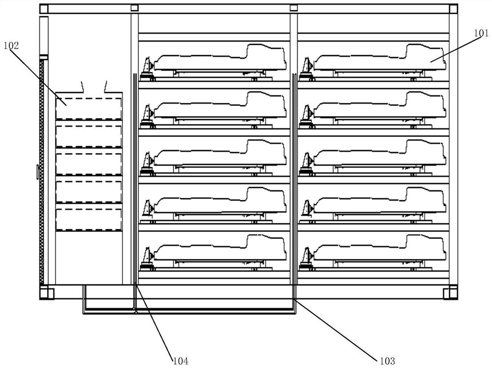
technical field [0001] The invention relates to the field of new energy vehicles, in particular to a charging unit for a quick-change battery of an electric vehicle, a switching station for an electric vehicle, and an energy storage station. Background technique [0002] Traditional substations use centralized wiring. The charger is installed in a cabinet with a drawer layout. Each charging cabinet is equipped with 6-7 chargers, and each power station is equipped with 4-5 (or even more) charging cabinets. In order to save installation space, these charging cabinets are centrally arranged in a separate space of the entire power exchange station (this space is used to arrange power distribution and air conditioning devices), while the battery rack is arranged in another space of the power exchange station, called the charging room. Each charger in the charging cabinet outputs 2 DC output power cables and a set of charging control cables. [0003] figure 1 The layout of the...

Claims


Application Information

Patent Timeline
Patent Type & Authority Applications(China)
IPC IPC(8): B60L53/14B60L53/30B60L53/80
CPCB60L53/14B60L53/30B60L53/80Y02T10/70Y02T10/7072Y02T90/12Y02T90/14
Inventor 张建平陆文成
Owner AULTON NEW ENERGY AUTOMOTIVE TECHNOLOGY GROUP
Learn More