Infrared laser coherent synthesis device and synthesis method

A technology of coherent synthesis and infrared laser, applied in the direction of laser devices, etc., can solve the problems of limited application and few synthesis channels

Active Publication Date: 2021-06-29
INST OF FLUID PHYSICS CHINA ACAD OF ENG PHYSICS
View PDF12 Cites 0 Cited by
  • Summary
  • Abstract
  • Description
  • Claims
  • Application Information

AI Technical Summary

Problems solved by technology

The currently reported quantum cascade laser coherent combination based on the external cavity method and interferometer structure h

Method used


Image

  • Infrared laser coherent synthesis device and synthesis method
  • Infrared laser coherent synthesis device and synthesis method

Examples


Embodiment 1

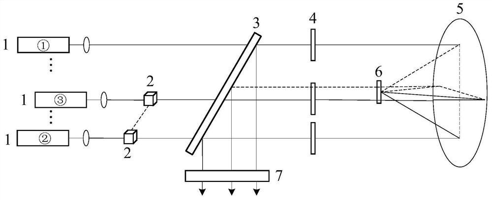
[0028] This embodiment provides an infrared laser coherent combination device, which is a mid-infrared quantum cascade laser coherent combination device based on polarization splitting mutual injection and phase-locking. The inner cavity polarization coupling output is used, such as figure 1 As shown, it is composed of a polarization splitter prism 2, a polarizer 3, a half-wave plate 4, a rotating parabolic mirror 5, a mirror 6, an output mirror 7 and 2N lasers 1, and the rear surface of the laser 1 and the output mirror 7 are mutual injection locks. The end mirror of the phase cavity, N is a positive integer ≥ 1; in the inter-injection phase-locked cavity, along the transmission direction of the optical path, a polarization beam splitter 2, a polarizer 3, a half-wave plate 4, a rotating parabolic mirror 5 and a reflection Mirror 6.

[0029] Each laser 1 adopts a quantum cascade laser, and the rear surface of the laser 1 is coated with an anti-reflection film, and the front s...

Embodiment 2

[0036] This embodiment provides an infrared laser coherent combination method, using the infrared laser coherent combination device provided in Example 1, and the specific combination path is as follows:

[0037] (1) Coherent combination of two laser beams emitted by two groups of lasers 1 arranged symmetrically in the center: laser light is emitted by any one of the two groups of lasers 1 arranged symmetrically, and passes through a polarizer 3, a half-wave plate 4, and a rotating paraboloid After the mirror 5 and the reflector 6 act, they are injected into another laser 1 in the two groups of lasers 1 arranged symmetrically in the center, and the injected laser light will affect the laser oscillation in the two lasers 1 arranged symmetrically in the center, realizing Phase locking of two lasers;

[0038] The coherent combination path of two lasers emitted by two groups of lasers 1 arranged symmetrically is as follows:

[0039] The laser light emitted by one of the two laser...


PUM


Abstract

The invention discloses an infrared laser coherent combination device and method. The infrared laser coherent combination device comprises an output mirror and laser devices, wherein the rear surfaces of the laser devices and the output mirror are end mirrors of a mutual injection phase-locked cavity, and all the laser devices are annularly arranged according to the center symmetry; a polarization splitting prism is used for realizing mutual energy injection of two asymmetrical laser devices; a polaroid is used for guaranteeing the polarization direction of laser output by the laser devices and meanwhile is used for achieving mutual energy injection of the two paths of symmetrical laser devices; a half-wave plate is used for rotating the polarization direction of the laser device and is matched with the polaroid to change mutual injection energy; a rotating parabolic mirror has axial symmetry and central symmetry, and a reflecting mirror is arranged at the focus of the rotating parabolic mirror; and the reflecting mirror reflects the laser reflected by the rotating parabolic mirror to the centrosymmetric position of the reflecting mirror. The infrared laser coherent combination device has the advantages of being simple in structure, easy to implement, free of active phase detection and correction, good in expansibility, high in synthesis efficiency and the like, and enables coherent synthesis of intermediate infrared quantum cascade lasers with more paths and higher power to be possible.

Description

technical field [0001] The invention belongs to the technical field of laser coherent synthesis, specifically relates to the field of mid-infrared quantum cascade laser coherent synthesis, and further relates to an infrared laser coherent synthesis device, in particular to a mid-infrared quantum cascade laser coherence based on polarization splitting mutual injection phase-locking synthesis device. Background technique [0002] In recent years, mid-infrared lasers have played an increasingly important role in the fields of environmental monitoring, space communication, trace gas measurement, and photoelectric countermeasures. Especially in the field of infrared countermeasures, airborne infrared light sources are needed to blind or interfere with photodetectors. Therefore, mid-infrared lasers with high power, good beam quality, compact structure and high reliability are very important light sources. With the development and progress of semiconductor laser technology, the em...

Claims


Application Information

Patent Timeline
IPC IPC(8): H01S3/23
CPCH01S3/23
Inventor 彭英楠赵祥杰胡奇琪李大鹏乔冉谭福利
Owner INST OF FLUID PHYSICS CHINA ACAD OF ENG PHYSICS
Why Eureka
Try Eureka