Linear motor and electric tool with buffering function at extreme position

A limit position and linear motor technology, applied in the field of buffers, can solve problems such as insufficient control, achieve the effect of reducing power loss, avoiding excessive impact, and ensuring normal operation

Pending Publication Date: 2021-06-29
苏州品匠机电技术有限公司
View PDF0 Cites 0 Cited by
  • Summary
  • Abstract
  • Description
  • Claims
  • Application Information

AI Technical Summary

Problems solved by technology

[0005] The purpose of the present invention is to overcome the deficiencies in the technology of ordinary linear motor control that is not in place, such as the linear motor control technology that does not need a position sensor, or under the condition that the linear motor control technology is not perfect, to provide a buffer function at the limit position Linear Motors and Power Tools

Method used


Image

  • Linear motor and electric tool with buffering function at extreme position
  • Linear motor and electric tool with buffering function at extreme position
  • Linear motor and electric tool with buffering function at extreme position

Examples


Embodiment Construction

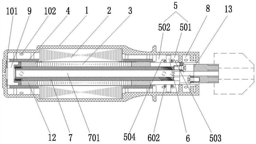
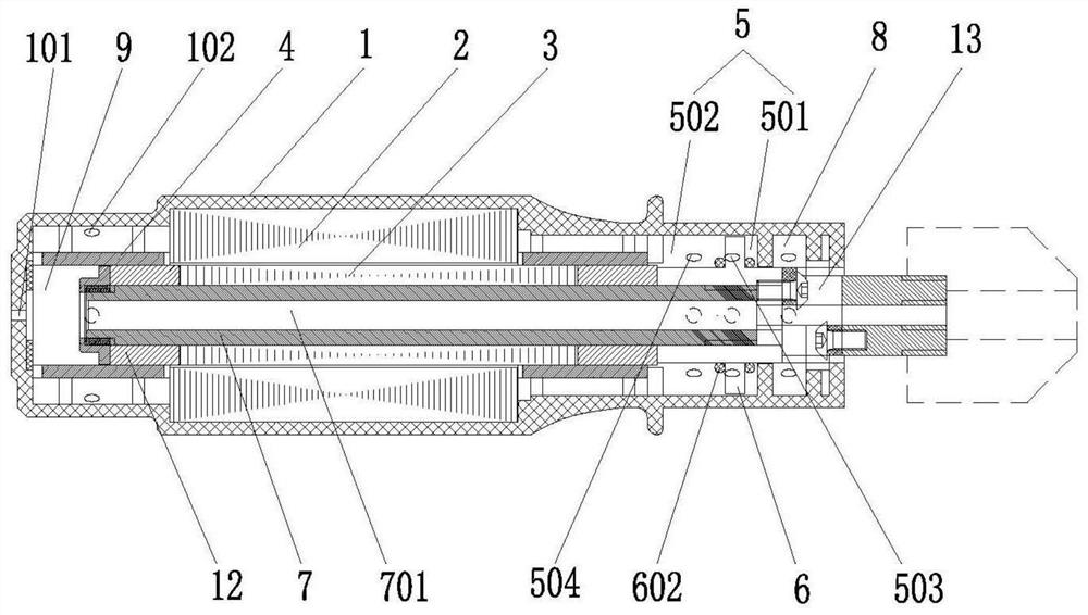
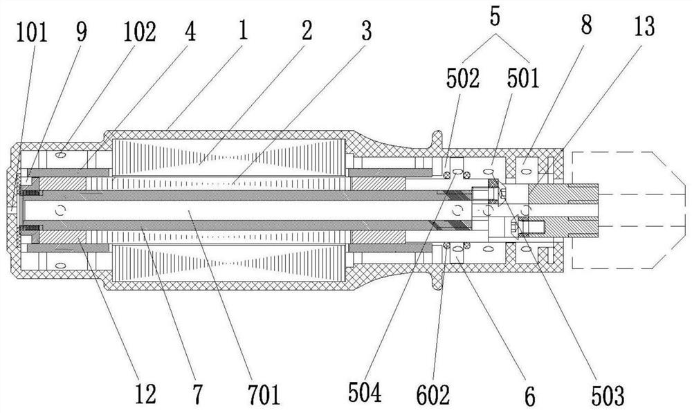
[0028] The present invention will be described in detail below in conjunction with specific embodiments shown in the accompanying drawings. However, these embodiments are not limited to the present invention, and structural, method, or functional changes made by those skilled in the art according to these embodiments are included within the protection scope of the present invention.

[0029] In the description of the scheme, it should be noted that the terms "center", "upper", "lower", "left", "right", "front", "rear", "vertical", "horizontal", " The orientation or positional relationship indicated by "inner", "outer", etc. is based on the orientation or positional relationship shown in the drawings, and is only for the convenience of description and simplification of description, rather than indicating or implying that the device or element referred to must have a specific orientation , constructed and operated in a particular orientation and therefore should not be construed...


PUM


Abstract

The invention discloses a linear motor and an electric tool with a buffering function at an extreme position, the linear motor comprises a stator assembly, a rotor assembly and a supporting and positioning piece which are arranged in a shell, the rotor assembly does linear reciprocating motion in the stator assembly and the supporting and positioning piece, a buffering cavity is arranged in the shell, a piston body which moves synchronously with the rotor assembly is fixedly connected to the rotor assembly, the piston body is arranged in the buffer cavity in a sliding mode and divides the buffer cavity into a first cavity body and a second cavity body, a first vent hole and a second vent hole are formed in the side wall of the buffer cavity, and when the piston body moves to the limiting position of the first cavity body or the second cavity body, the piston body blocks or exceeds the first vent hole or the second vent hole and compresses fluid in the first cavity or the second cavity, so that an air pressure difference is formed between the first cavity and the second cavity, and the piston body is buffered. According to the invention, a buffering effect is achieved when the mover assembly runs to a limit position, the impact of the mover assembly on the shell is reduced, and meanwhile, enough power is kept without loss in most of the time in the running process.

Description

technical field [0001] The invention relates to the technical field of buffers, in particular to a linear motor with a buffer function at an extreme position and a power tool using the buffer. Background technique [0002] With the continuous improvement of living conditions, people have higher and higher requirements for all aspects of life. Therefore, various daily necessities and electrical products used in people's lives are constantly being introduced. Linear motor is a new type of direct drive technology developed recently. Due to the outstanding advantages of linear motors such as zero transmission chain, no contact, no backlash, high rigidity, and fast response, linear motors are gradually becoming the core functional components of linear motion products. [0003] In the application of linear power machine derivative products, such as linear power electric tools, civil tools, etc., they are not pure pump bodies, but may be other pure application power tools, such as...

Claims


Application Information

Patent Timeline
IPC IPC(8): H02K41/02H02K5/20
CPCH02K5/20H02K41/02
Inventor 胡方坤
Owner 苏州品匠机电技术有限公司
Why Eureka
Try Eureka