Catamenial fluid removal
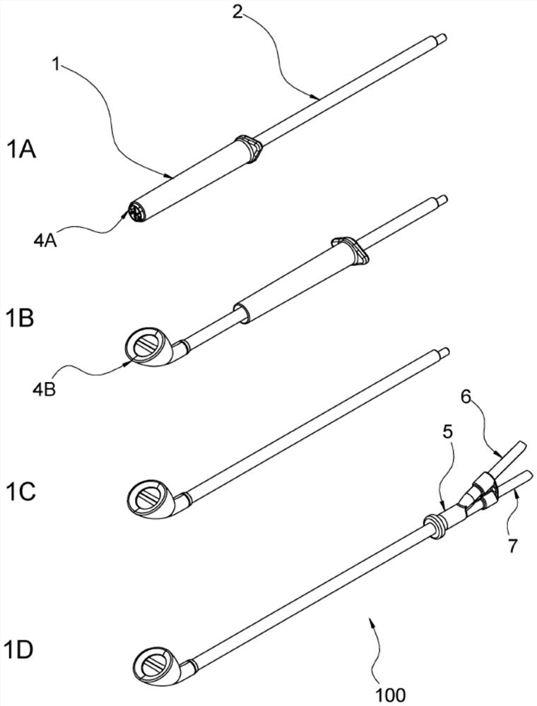
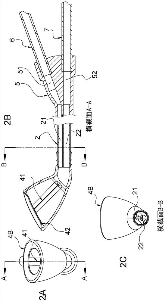
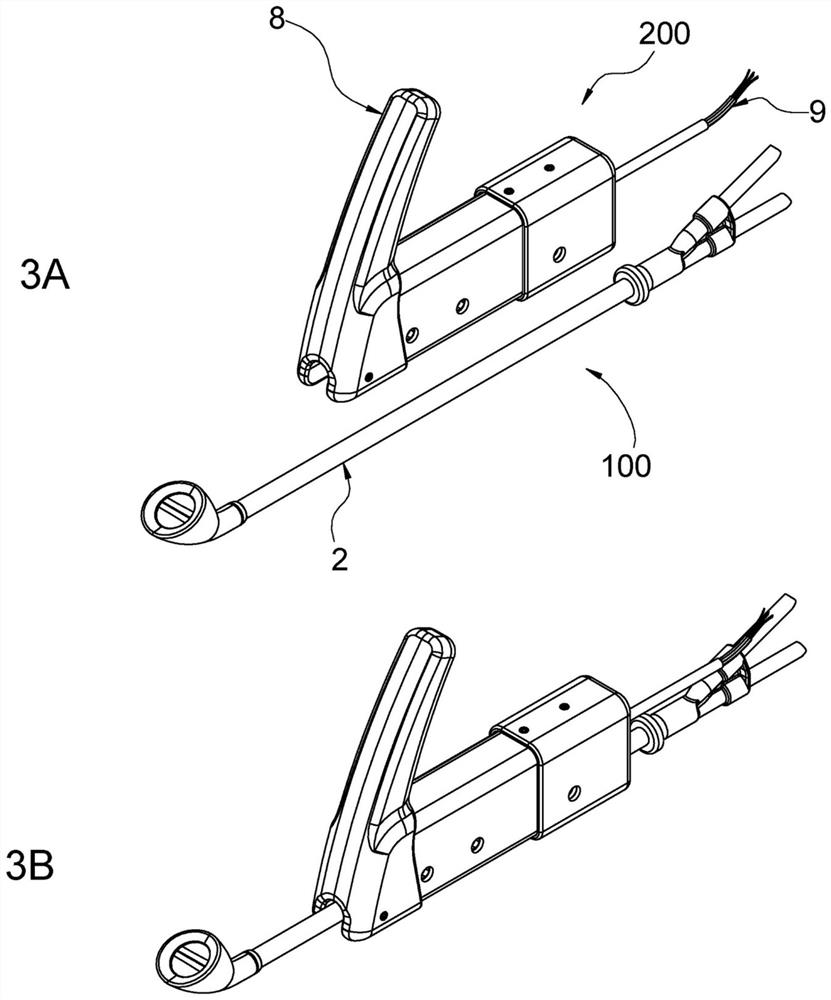
A fluid and menstrual technology, applied in the fields of menstrual management, devices for sucking out uterine fluid, and devices for removing uterine and vaginal fluids to relieve inconvenience and discomfort
- Summary
- Abstract
- Description
- Claims
- Application Information
AI Technical Summary
Problems solved by technology
Method used
Image
Examples
example 1
[0080] Compare models
[0081] Several models were prepared as follows. Such as Figure 20 As seen, the uterus model is made of TPE and includes a chamber, an orifice (cervix) placed in the model vagina, a filling catheter (through which a model blood or water filled tube is inserted) and another catheter (e.g. can be used for pressure measurement ). The uterus model is installed on the support with a clamp so that the uterus body is perpendicular to the ground. A stopper is placed to seal the cervical ostium and the pressure measuring catheter. The scale is placed directly below the bracket. An empty bowl is placed below the uterus to allow water to collect. A tube connected to the bottle is inserted into the filling conduit. The pressure column is filled with a fixed amount (600 grams) of water. The plug sealing the cervical opening is removed. The differential model was characterized by allowing water to flow through the orifice into the bowl while continuously me...
example 2
[0083] model uterus expulsion
[0084] Preparation of an endometrial fragment simulant designed to simulate menstruation (termed menstruation) consisting of artificial mucus (wet endometrial fragments) and pieces of artificial dry mucus (dry endometrial pieces, measuring 10 mm x 5 mm x 5 mm). A suction cup connected to a suction tube is configured to wrap around the cervix. Rotary valve ( Figure 20 507 in ) controls the vacuum pressure oscillations generated by the vacuum pump; it has two working configurations, one for connecting the suction cup to vacuum and one for disconnecting it. In some embodiments, the suction cup is provided with a vacuum relief valve. A stopper is inserted into the cervical ostium and the pressure measuring catheter to seal it. Dried endometrial fragments (mock) with a total mass of approximately 3.5 grams were inserted through the filling catheter into the uterine cavity. The mass of the filled uterus is measured and the mass of the dried en...
example 3
[0104] Another experiment mimicking the aspiration of menstrual fluid from the uterus by applying vacuum pressure to the cervical ostium was performed as follows. A TPE model of the uterus was filled with 8.00 grams to 8.25 grams of artificial mucus simulating menstruation (endometrial fragments, wet only) and mounted on a vaginal simulator. The uterus was then connected by one of its filling catheters to a bottle filled with blood simulant to create an intrauterine pressure of 50 mbar. Vacuum pressure (various pressures and frequencies, see Table 4) is applied to the cast orifice (cervical canal) to expel intrauterine menses through a flexible plastic suction cup connected to the pump suction receptacle. A pressure transducer connected to a data logger continuously measures (at a sampling rate of 2 Hz) the pressure in the suction vessel, as well as the pressure occurring in the immediate vicinity of the cervix inside the uterus or in the suction tube. The nominal vacuum pres...
PUM
 Abstract
Description
Claims
Application Information
 - R&D
- Intellectual Property
- Life Sciences
- Materials
- Tech Scout
- Unparalleled Data Quality
- Higher Quality Content
- 60% Fewer Hallucinations
Browse by: Latest US Patents, China's latest patents, Technical Efficacy Thesaurus, Application Domain, Technology Topic, Popular Technical Reports.
© 2025 PatSnap. All rights reserved.Legal|Privacy policy|Modern Slavery Act Transparency Statement|Sitemap|About US| Contact US: help@patsnap.com


