Supercharge Your Innovation With Domain-Expert AI Agents!

Integrated bristle production equipment

A technology for production equipment and bristles, which is applied in the field of integrated production equipment for bristles, can solve problems such as low efficiency and manpower consumption, and achieve the effects of ensuring efficiency, high work efficiency, and increasing the contact area

Active Publication Date: 2021-07-02
安徽三和刷业股份有限公司
View PDF24 Cites 0 Cited by
  • Summary
  • Abstract
  • Description
  • Claims
  • Application Information

AI Technical Summary

Problems solved by technology

[0004] The purpose of the present invention is to solve the problem of labor-intensive and low efficiency in the prior art, and propose an integrated production equipment for bristles

Method used


Image

  • Integrated bristle production equipment
  • Integrated bristle production equipment
  • Integrated bristle production equipment

Examples


Embodiment 1

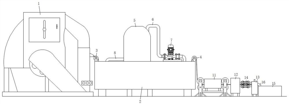
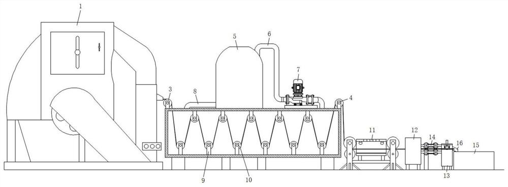
[0033] refer to Figure 1-6, an integrated production equipment for brush hairs, comprising a wire drawing machine 1 and a condensing box body 2, mounting seats-3 are fixed on both sides of the top surface of the condensing box body 2, and two mounting seats-3 on the same side are rotatably connected The reversing roller 4, a liquid condenser 5 is also arranged on the rear side of the condensation box 2, the input end of the liquid condenser 5 is connected with the top side of the condensation box 2, and a suction pipe 6 is connected, and a water pump 7 is also installed on the suction pipe 6 , the top side of the condensing box 2 is also connected with the water inlet pipe 8 on the other side of the top surface of the condensing box 2, and the inner bottom surface and the top surface of the condensing box 2 are also fixed with a mounting seat 2 9, two mounting seats 9 in the same group There are guide rollers 10 connected in rotation between them, and the bristles are wound b...

Embodiment 2

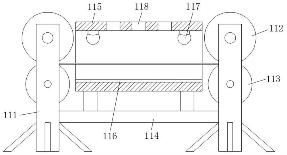
[0035] Such as figure 1 , 2 As shown in and 6, the present embodiment is basically the same as Embodiment 1. Preferably, the traction mechanism 14 includes two installation bars 141, and the upper and lower ends of the four installation bars two 141 sides are rotatably connected with installation rods 142, and the two installation bars 141 The outer walls are all fixedly connected with transmission rollers 143 by screws, the front sides of the two transmission rollers 143 at the upper and lower ends pass through the installation strip 141 and are rotatably connected by the conveyor belt 144, and the rear sides of the two transmission rollers 143 on the same side also pass through the installation strip two. 141 and is connected through the rotation of gear set 145, and one side of the rear end of the installation bar two 141 is also provided with a support seat 146, and the top surface of the support seat 146 is fixedly connected with a servo motor 147 by screws, and the outpu...

Embodiment 3

[0039] Such as figure 1 , 2 As shown in and 5, this embodiment is basically the same as Embodiment 1. Preferably, both sides of the top surface of the cutting hole 132 are fixed with electric telescopic rods 136 by screws, and the output ends of the electric telescopic rods 136 are all connected with U by screws. Shaped frame 137, U-shaped frame 137 front and back side inner walls are rotatably connected with pressure roller 138.

[0040] In this embodiment, when cutting, the electric telescopic rod 136 drives the electric telescopic rod 136 to move down so that the pressure roller 138 and the bristles are lifted together, thereby realizing the limit and fixing of both sides of the cut bristles, and then providing a certain amount for the stable cutting of the bristles. protection.


PUM


Abstract

The invention discloses integrated bristle production equipment which comprises a wire drawing machine and a condensation box body; first mounting bases are fixed to the two sides of the top face of the condensation box body correspondingly; a reversing roller is rotationally connected between the two first mounting bases on the same side; a liquid condenser is further arranged on the rear side of the condensation box body; the input end of the liquid condenser and one side of the top face of the condensation box body are connected with a water pumping pipe in a penetrating mode; a water pump is further installed on the water pumping pipe; the top side of the condensation box body and the other side of the top face of the condensation box body are further connected with a water inlet pipe in a penetrating mode; second mounting bases are further fixed to the inner bottom face and the inner top face of the condensation box body; guide rollers are rotationally connected between the two second mounting bases in the same set; and a detection device is further arranged on the side, away from the wire drawing machine, of the condensation box body and comprises a fixing frame. The integrated bristle production equipment is reasonable in design and high in working efficiency, integrated machining operation of bristles can be achieved, the bristle machining speed is high, the bristle machining quality is high, and the requirement for efficient batch production of the bristles is well met.

Description

technical field [0001] The invention relates to the technical field of brush hair processing equipment, in particular to an integrated production equipment for brush hair. Background technique [0002] The bristles are mostly mixed with various ingredients and drawn by a wire drawing machine, and then the bristles are cooled, tested, tied and cut and used as raw materials for flocking, so it is particularly important for the high-quality production of bristles. [0003] The existing bristles are usually prepared by using a wire drawing machine to draw and condense and pack them, and then detect the bristles, which needs to continuously transfer the working position of the bristles during the preparation of the bristles. The operation is cumbersome, which greatly affects the quality of the bristles processing , and the accuracy of the existing detection device is poor, so it is necessary to study a kind of bristle integrated production equipment. Contents of the invention ...

Claims


Application Information

Patent Timeline
Patent Type & Authority Applications(China)
IPC IPC(8): A46D1/04A46D1/06B29C35/16B29C37/00B26D7/02G01N21/88
CPCA46D1/04A46D1/06B29C35/16B29C37/00B26D7/02G01N21/88B29C2035/1616B29C2037/90Y02P70/10
Inventor 胡爽徐东海徐小祥
Owner 安徽三和刷业股份有限公司
Features
  • R&D
  • Intellectual Property
  • Life Sciences
  • Materials
  • Tech Scout
  • Unparalleled Data Quality
  • Higher Quality Content
  • 60% Fewer Hallucinations
Learn More