
Matched drill boom facility of mining equipment bucket

A technology for mining equipment and drilling arms, applied in the field of equipment processing, can solve the problems of shape and position tolerance of bucket ear plate holes, inconsistency of bucket ear plate holes, repeated positioning errors, etc. The effect of machining accuracy

Pending Publication Date: 2021-07-02
张芳
View PDF1 Cites 2 Cited by
  • Summary
  • Abstract
  • Description
  • Claims
  • Application Information

AI Technical Summary

Problems solved by technology

[0005] The purpose of the present invention is to provide a matching drill arm facility for mining equipment buckets, to solve the problem that the existing bucket ear plate hole processing proposed in the above-mentioned background technology needs to be drilled one by one or a long drill bit is used for drilling, but one by one Drilling with holes is prone to repeated positioning errors, which affects the shape and position tolerance of the bucket ear plate holes. At the same time, when drilling through the long-arm drill bit, the drill bit is prone to vibration, resulting in inconsistent problems in the bucket ear plate holes.

Method used


Image

  • Matched drill boom facility of mining equipment bucket
  • Matched drill boom facility of mining equipment bucket
  • Matched drill boom facility of mining equipment bucket

Examples


Embodiment Construction

[0028] The following will clearly and completely describe the technical solutions in the embodiments of the present invention with reference to the accompanying drawings in the embodiments of the present invention. Obviously, the described embodiments are only some, not all, embodiments of the present invention.

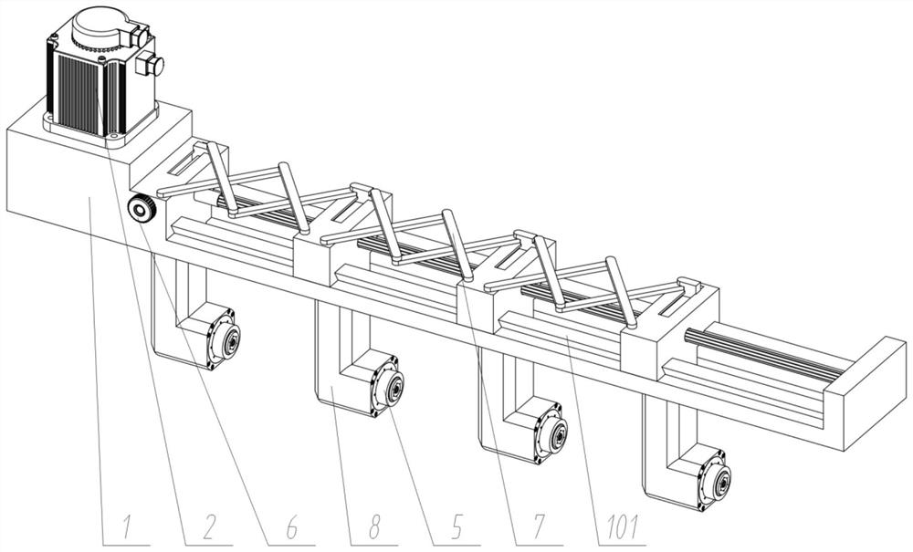
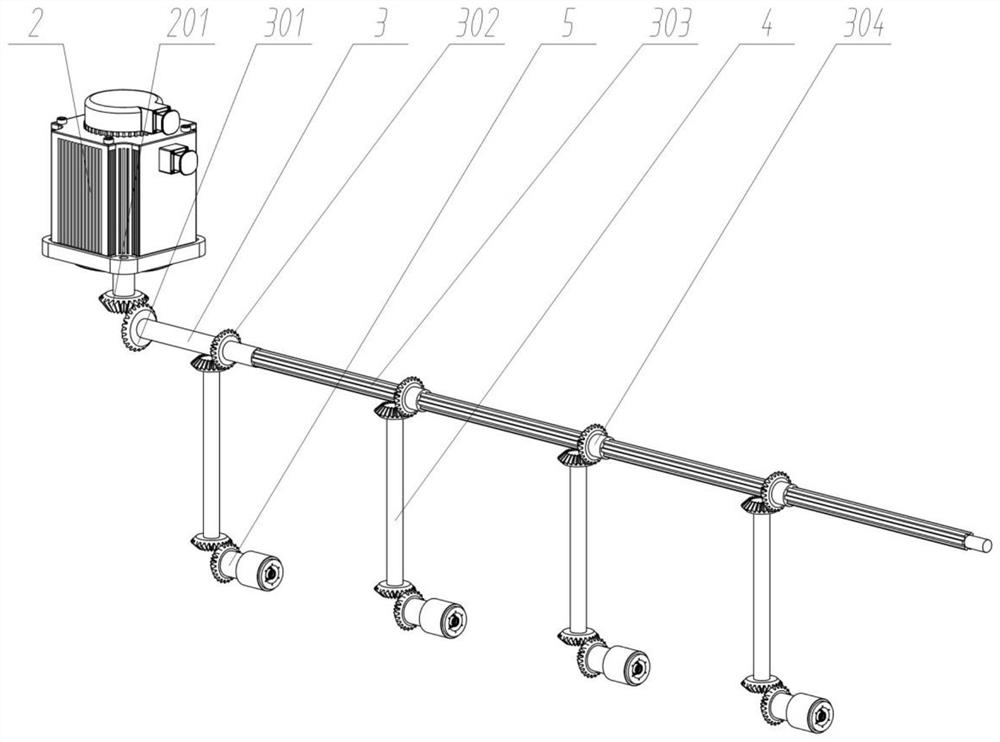
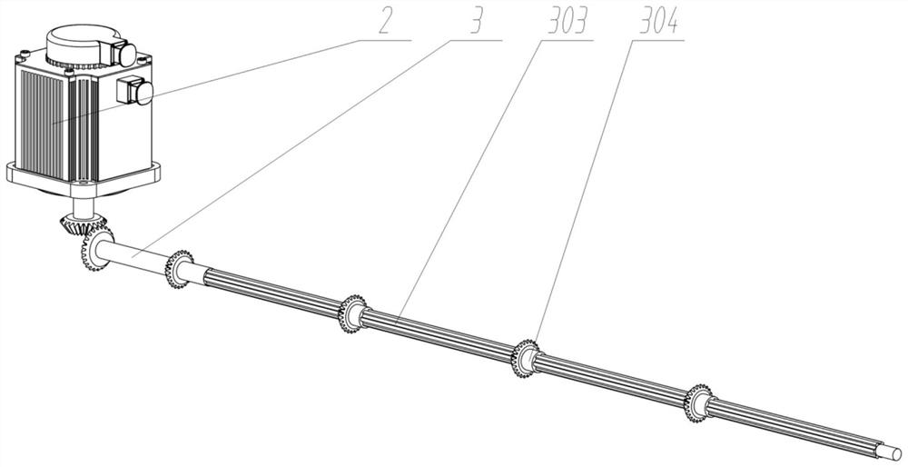
[0029] see Figure 1 to Figure 8 , an embodiment provided by the present invention: a supporting drill arm facility for mining equipment buckets, including a drill arm main body 1; a group of drilling drive parts 2 are fixedly connected to the left top of the drill arm main body 1; There is a group of drilling intermediate transmission horizontal shafts 3 in the internal rotation connection; four sets of drilling seats 8 are arranged on the lower part of the drilling arm main body 1; a group of drilling seat 8 on the left is fixedly connected with the drilling arm main body 1; The three groups of drilling bases 8 on the side are slidingly connected with the main body...


PUM


Abstract

The invention discloses a matched drill boom facility of a mining equipment bucket, relates to the technical field of equipment processing, and solves the problems that repeated positioning errors easily occur during the processing of existing bucket lug plate holes, the form and location tolerance of the bucket lug plate holes is influenced, and the bucket lug plate holes are inconsistent. The matched drill boom facility comprises a drill boom body, wherein the top of the left side of the drill boom body is fixedly connected with a group of drilling driving pieces, a group of drilling middle transmission transverse shafts are rotationally connected into the drill boom body, and four groups of drilling bases are uniformly arranged at the lower part of the drilling boom body. By arranging the four groups of drilling bases, four groups of holes in a vertical plate can be drilled at the same time, the working efficiency is improved, meanwhile, repeated positioning errors are avoided, the machining precision is guaranteed, the problem that bucket lug plate holes are inconsistent is effectively solved, meanwhile, the distances between the four groups of drilling bases are evenly adjusted and can be adjusted according to needs in use, machining of buckets of different models is met, practicability is improved, and adjusting operation is easy.

Description

technical field [0001] The invention relates to the technical field of equipment processing, in particular to a matching drill arm facility for a mining equipment bucket. Background technique [0002] A bucket refers to a bucket installed on an excavating machine, also called a bucket. The bucket consists of a tooth seat plate, a bottom plate, a side plate, a wall plate, a lug plate, a back plate, a bucket ear plate, a bucket ear cover, and a bucket tooth. , tooth seat, guard plate or bucket angle and other spare parts, among which the bucket ear plate is mainly used for the connection of the bucket. Generally, there are multiple sets of bucket ear plates on the bucket to improve the installation stability. Generally, it is used with the shaft sleeve, and the drilling machine is often used for the hole processing of the bucket ear plate. [0003] For example, application number: CN201510013735.2 The present invention belongs to the technical field of mechanical processing e...

Claims


Application Information

Patent Timeline
Patent Type & Authority Applications(China)
IPC IPC(8): B23B39/16B23Q1/01
CPCB23B39/16B23Q1/01
Inventor 张芳
Owner 张芳
Learn More