Ultralow-emission denitration equipment for cement production

An ultra-low, denitrification technology, applied in separation methods, dispersed particle separation, chemical instruments and methods, etc., can solve the problems of incomplete flue gas denitration, decreased denitration efficiency, and easily blocked SCR denitration catalysts.

Inactive Publication Date: 2021-07-06
中材萍乡水泥有限公司
View PDF7 Cites 2 Cited by
  • Summary
  • Abstract
  • Description
  • Claims
  • Application Information

AI Technical Summary

Problems solved by technology

[0004] In view of the above situation, in order to overcome the defects of the prior art, the present invention provides an ultra-low emission denitrification equipment for cement production, which effectively so

Method used


Image

  • Ultralow-emission denitration equipment for cement production
  • Ultralow-emission denitration equipment for cement production
  • Ultralow-emission denitration equipment for cement production

Examples


Embodiment 1

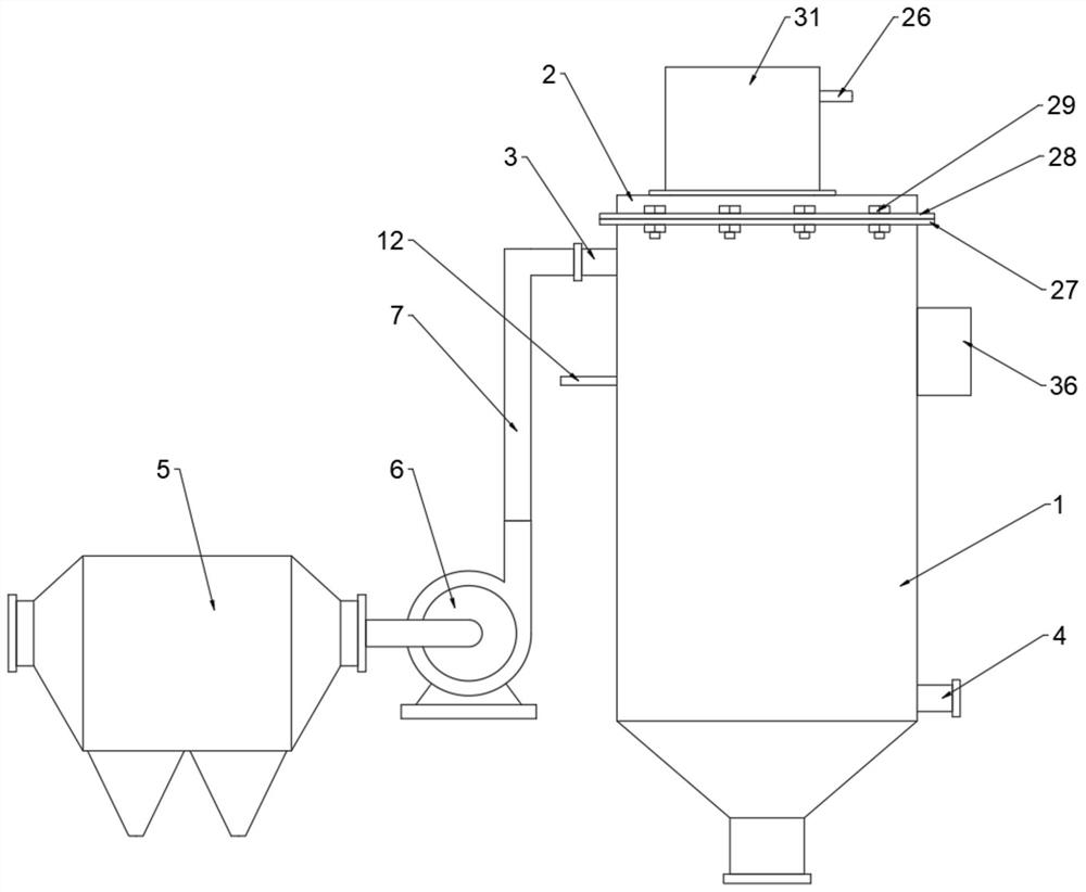
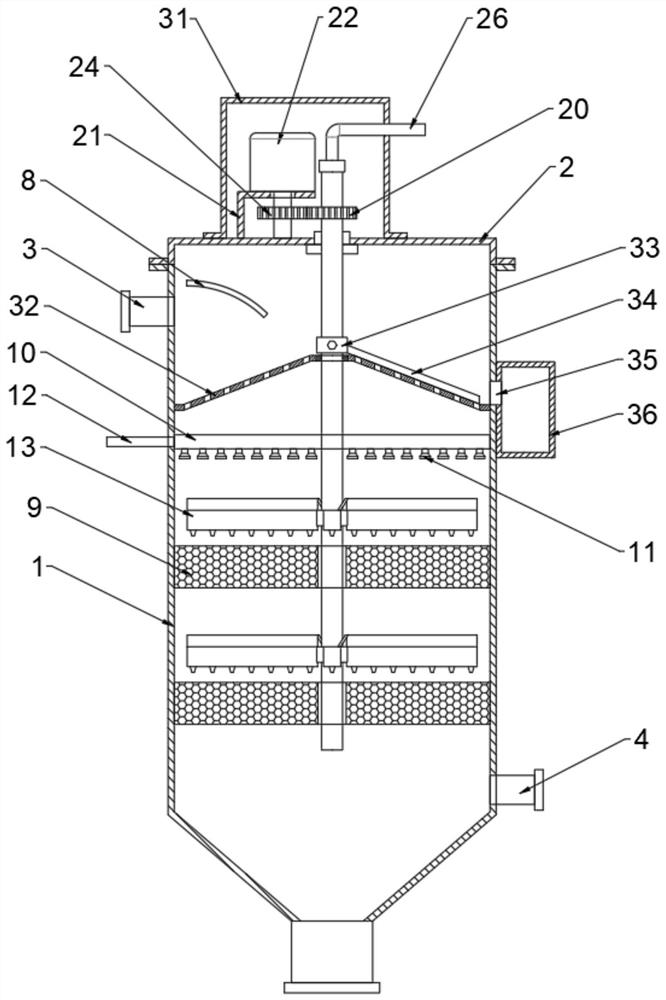
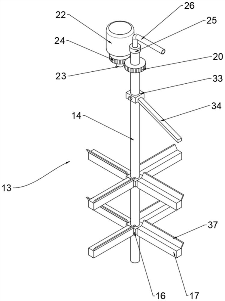
[0029] Embodiment one, by Figure 1-Figure 6 Given, the present invention includes a reaction cylinder 1, the upper end of the reaction cylinder 1 is connected with a cylinder cover 2, the upper side of the reaction cylinder 1 is connected with an air inlet pipe 3, the lower part of one end of the reaction cylinder 1 is connected with an outlet pipe 4, and one side of the reaction cylinder 1 is installed There is an electric precipitator 5, the output end of the electric precipitator 5 is connected with a fan 6, and the output end of the fan 6 is connected with the air inlet pipe 3 through the smoke pipe 7, and the side of the air inlet pipe 3 is connected with a slow flow pipe relative to the inside of the reaction cylinder 1. A catalyst layer 9 is uniformly connected to the inside of the plate 8 and the reaction cylinder 1, and an ammonia injection pipeline 10 is connected above the catalyst layer 9, and an atomizing nozzle 11 is evenly installed at the lower end of the ammon...

Embodiment 2

[0031] Embodiment 2, on the basis of Embodiment 1, the upper end of the reaction cylinder 1 is welded with a first flange ring 27, the lower end of the cylinder cover 2 is connected with a second flange ring 28, the first flange ring 27 and the second flange ring 28 is connected by bolts 29, and the first flange ring 27 and the second flange ring 28 are fixed under the connection of bolts 29, so that the cylinder cover 2 and the reaction cylinder 1 can be opened and closed conveniently, and then it is convenient to check the inside of the reaction cylinder 1. Component repair and maintenance.

Embodiment 3

[0032] Embodiment 3, on the basis of Embodiment 1, the inner upper wall of the bronchial cavity 18 is evenly connected with a deflector 30, and the deflector 30 gradually grows obliquely along the airflow blowing direction, and the main air cavity can be divided by the deflector 30. The airflow flowing in the channel 15 is directed downwards so that the airflow blows downwards.


PUM


Abstract

The invention relates to the technical field of cement production, and discloses ultra-low emission denitration equipment for cement production, and solves the problems of incomplete denitration of flue gas discharged during cement processing at present, easy blockage of an SCR denitration catalyst and reduction of denitration efficiency. The equipment comprises a reaction cylinder, the upper end of the reaction cylinder is connected with a cylinder cover; one side of the upper part of the reaction cylinder is connected with a gas inlet pipeline, and the lower part of one end of the reaction cylinder is connected with a gas outlet pipeline. According to the invention, through the arrangement of the dust blowing mechanism, the blockage of the catalyst layer is effectively avoided so that the denitration reaction effect is good; through the arrangement of the spoiler, the rotating shaft rotates to drive the blowing pipeline to rotate, and the spoiler rotates along with the blowing pipeline to flap airflow in the reaction cylinder so that the turbulence of the airflow is increased, the airflow in the reaction cylinder is disordered, the contact time of flue gas between catalyst layers is prolonged, the flue gas can be in full contact with the catalyst layer, and thus the denitration reaction efficiency is improved, the denitration effect is better, and ultralow emission is realized.

Description

technical field [0001] The invention belongs to the technical field of cement production, in particular to ultra-low emission denitrification equipment for cement production. Background technique [0002] In recent years, the emission of nitrogen oxides (NOx) in my country's cement industry has shown a rapid growth trend, and it has become the third largest source of NOx emissions after thermal power and motor vehicles. The country will promote the control of NOx emissions from other industries, mainly the cement industry. With the tightening of environmental protection policies, the NOx standards of the cement industry are becoming more and more stringent. Enterprise NOx emission ≤ 400mg / Nm 3 , adjusted to ≤320mg / Nm in key areas 3 . Many provinces and cities have introduced stricter local standards, and Henan Province has raised the standard below, requiring NOx emissions to be ≤100mg / Nm 3 , while the maximum denitrification efficiency of SNCR is only 70%, which cannot ...

Claims


Application Information

Patent Timeline
IPC IPC(8): B01D53/86B01D53/56B01D53/88B01D50/00
CPCB01D53/8625B01D53/88B01D50/00B01D2258/0283B01D2251/2062
Inventor 马建军黎奉武张昌煜李志兵彭涛周庆周汉忠
Owner 中材萍乡水泥有限公司
Why Eureka
Try Eureka