
MCU verification method and system and terminal equipment

A verification method and technology to be verified, applied in the field of system and terminal equipment, MCU verification method, can solve the problems of high chip complexity and difficult verification work

Pending Publication Date: 2021-07-06
SHENZHEN YSPRING TECH
View PDF0 Cites 10 Cited by
  • Summary
  • Abstract
  • Description
  • Claims
  • Application Information

AI Technical Summary

Problems solved by technology

But the more functions the chip has, the higher the complexity of the chip and the more difficult the verification work will be

Method used

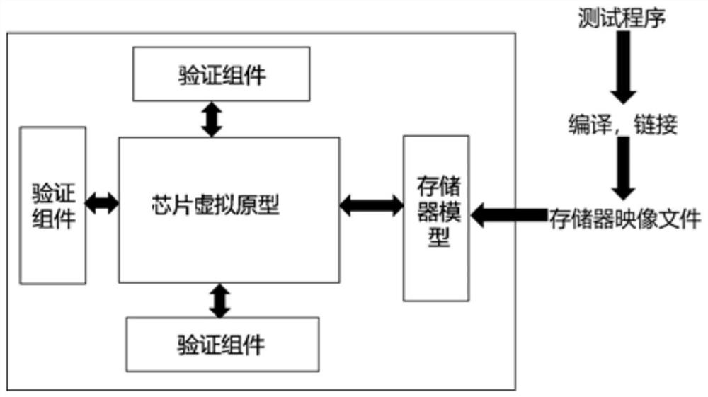

Image

  • MCU verification method and system and terminal equipment
  • MCU verification method and system and terminal equipment
  • MCU verification method and system and terminal equipment

Examples


Embodiment 1

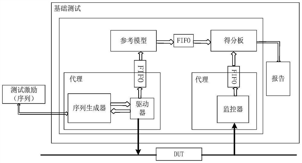
[0057] Please refer to figure 2 , this embodiment proposes an MCU verification method, which can be applied to a general verification platform. When the MCU needs to be verified, a connection between the MCU to be verified and the built general verification platform can be established, so that the general verification platform can be used to communicate with the MCU. interactively to verify that the MCU is functioning properly. In this embodiment, simulation verification will be performed based on the UVM verification platform.

[0058] see figure 2 A UVM verification platform architecture shown, exemplary, the UVM verification platform architecture may include a sequencer (sequencer), a driver (driver), a monitor (monitor), a scoreboard (scoreboard), an agent (agent) and Reference model (reference model) and other components, specifically through the transaction level to build the actual required verification platform. Such as figure 2 As shown, the sequencer is connec...

Embodiment 2

[0092] Please refer to Figure 7 , based on the method of the above-mentioned embodiment 1, this embodiment proposes an MCU verification system. Exemplarily, the MCU verification system includes an MCU to be verified and a general verification platform, and the general verification platform is connected to the MCU to be verified, wherein the general verification The platform is also built with the same reference model as the MCU function to be verified. In this embodiment, the universal verification platform can adopt the UVM verification platform in the first embodiment above.

[0093] Exemplarily, as figure 2As shown, the UVM verification platform mainly includes components such as a sequencer, a driver, a monitor, and a score board. The driver and the monitor are respectively connected to the MCU to be verified through a physical interface, and the sequencer is connected to the driver. The score boards are respectively connected through FIFO in turn, and the monitor is c...


PUM


Abstract

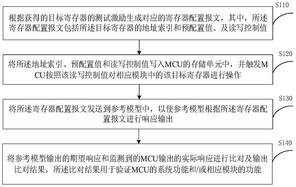
The embodiment of the invention provides an MCU verification method and system and terminal equipment. The method comprises the steps: generating a corresponding register configuration message according to the test excitation of a target register, and writing an address index and a pre-configuration value contained in the register configuration message into a storage unit of an MCU, so as to enable the MCU to operate the target register in a corresponding module; meanwhile, sending the configuration message to a reference model corresponding to the MCU, and varifying the system function of the MCU and / or the function of the corresponding module by comparing the expected response output by the reference model with the actual response output by the MCU. According to the method, most functions are put down to the module level for verification, only one unified module level simulation platform needs to be built; compared with an existing verification method, it is avoided that a large number of instruction programs need to be developed, and it is also avoided that many verification platforms need to be built for specific modules; according to the scheme, not only can the MCU be effectively verified, but also the utilization rate of a universal verification platform and the like are improved.

Description

technical field [0001] The present application relates to the technical field of chip verification, in particular to an MCU verification method, system and terminal equipment. Background technique [0002] With the development of IC (Integrated Circuit) process technology and EDA (Electronic Design Automation) design level, the ability and technology of using IP (Intellectual Property) core to design MCU (Microcontroller Unit, Micro Control Unit) has been greatly improved. The application of a unified bus specification can ignore the differences in ports between IP cores, making it easy to interconnect multiple IP cores, and can integrate the entire system, including microprocessors, on-chip buses, memory modules, and I / O peripherals, into In one chip, while realizing multiple functions, the area of ​​PCB (printed circuit board) is reduced, the reliability of the whole system is improved, and the power consumption of the equipment can also be reduced. But the more functions...

Claims


Application Information

Patent Timeline
IPC IPC(8): G06F11/263G06F11/273
CPCG06F11/263G06F11/273
Inventor 刘志刚庄腾飞
Owner SHENZHEN YSPRING TECH
Learn More