Hemodynamic force simulation method and device

A simulation method and blood flow technology, applied in the field of hemodynamic simulation, can solve the problems of low reliability and potential safety hazards of hemodynamic simulation

Pending Publication Date: 2021-07-06
BEIJING ESCOPE TECH CO LTD
View PDF5 Cites 5 Cited by
  • Summary
  • Abstract
  • Description
  • Claims
  • Application Information

AI Technical Summary

Problems solved by technology

[0004] Embodiments of the present invention provide a hemodynamic simulation method and device to at least solve the technical problem of low reliability of hemodynamic simulation due to potential safety hazards in the invasive fractional blood flow reserve measurement in the related art

Method used


Image

  • Hemodynamic force simulation method and device
  • Hemodynamic force simulation method and device
  • Hemodynamic force simulation method and device

Examples


Embodiment 1

[0043] According to an embodiment of the present invention, a method embodiment of a hemodynamic simulation method is provided. It should be noted that the steps shown in the flow charts of the accompanying drawings can be executed in a computer system such as a set of computer-executable instructions , and, although a logical order is shown in the flowcharts, in some cases the steps shown or described may be performed in an order different from that shown or described herein.

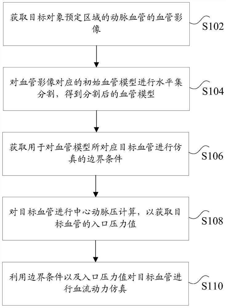
[0044] figure 1 is a flowchart of a hemodynamic simulation method according to an embodiment of the present invention, such as figure 1 As shown, the hemodynamic simulation method includes the following steps:

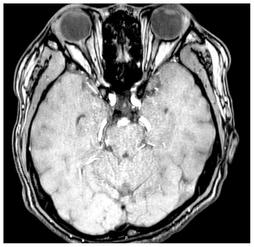
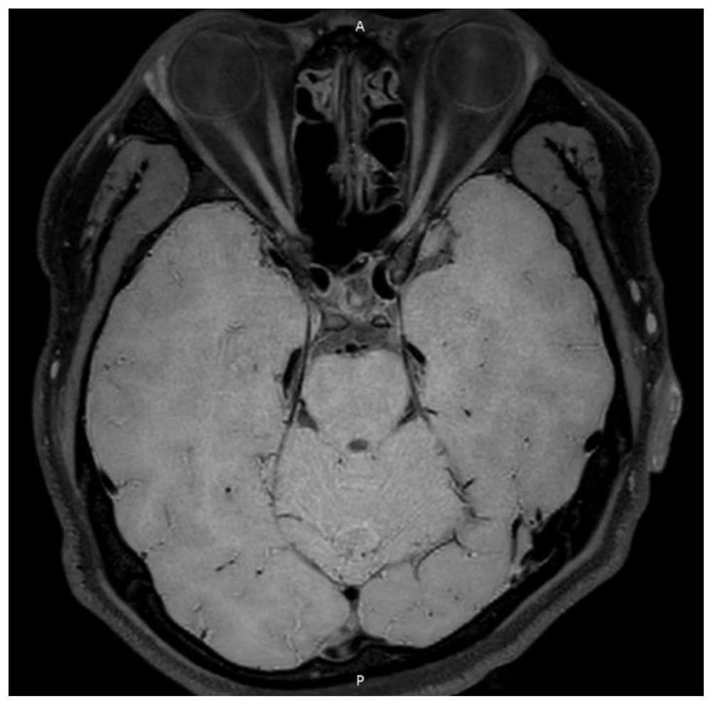
[0045] Step S102, acquiring blood vessel images of arteries in a predetermined region of the target object.

[0046] In this embodiment, the target object may be a human body, and the predetermined area may be an area containing arteries such as the head and neck. The vascular images here ar...

Embodiment 2

[0093] According to another aspect of the embodiments of the present invention, a hemodynamic simulation device is also provided, Figure 10 is a schematic diagram of a hemodynamic simulation device according to an embodiment of the present invention, such as Figure 10 As shown, the hemodynamic simulation device includes: a first acquisition unit 1001 , a level set segmentation unit 1003 , a second acquisition unit 1005 , a third acquisition unit 1007 and a simulation unit 1009 . The hemodynamic simulation device will be described in detail below.

[0094] The first acquisition unit 1001 is configured to acquire blood vessel images of arteries in a predetermined area of ​​a target object.

[0095] The level set segmentation unit 1003 is configured to perform level set segmentation on the initial vessel model corresponding to the vessel image to obtain a segmented vessel model.

[0096] The second obtaining unit 1005 is configured to obtain boundary conditions for simulating...

Embodiment 3

[0110] According to another aspect of the embodiments of the present invention, there is also provided a computer-readable storage medium, the computer-readable storage medium includes a stored computer program, wherein when the computer-readable storage medium is executed by a processor, the computer-readable storage medium is controlled. The device where the medium is located executes any one of the hemodynamic simulation methods described above.


PUM


Abstract

The invention discloses a hemodynamic force simulation method and device. The method comprises the following steps: acquiring a blood vessel image of an artery blood vessel in a predetermined area of a target object; performing level set segmentation on an initial blood vessel model corresponding to the blood vessel image to obtain a segmented blood vessel model; acquiring a boundary condition for simulating a target blood vessel corresponding to the blood vessel model; performing central arterial pressure calculation on the target blood vessel to obtain an inlet pressure value of the target blood vessel; and performing hemodynamic simulation on the target blood vessel by using the boundary condition and the inlet pressure value. The technical problem that in the related technology, potential safety hazards exist in invasive fractional flow reserve measurement, and consequently the reliability of hemodynamic simulation is low is solved.

Description

technical field [0001] The present invention relates to the technical field of hemodynamic simulation, in particular to a hemodynamic simulation method and device. Background technique [0002] Intracranial Atherosclerotic (ICAS) disease is the main cause of stroke. The SAMMPRIS trial showed that, even with optimal medical care, the annual stroke recurrence rate in patients with severe intracranial stenosis was as high as 12%. The VISSIT trial did not show the benefit of intracranial stenting. However, one reason for this is the relative inexperience with the use of devices and stenting procedures, leading to complications; another important factor is the failure to select patients with the highest risk of recurrent stroke. Optimal medical conditions alone are not enough, and many patients may benefit from vascular intervention. ICAS traditionally treats patients based on the degree of luminal stenosis. Hemodynamics, along with plaque characteristics, are important facto...

Claims


Application Information

Patent Timeline
Patent Type & Authority Applications(China)
IPC IPC(8): G06F30/28G06T7/12G06F113/08G06F119/14
CPCG06F30/28G06T7/12G06F2113/08G06F2119/14G06T2207/30101G06T2207/10088Y02T90/00
Inventor 张超赵清华毛益进刘伟
Owner BEIJING ESCOPE TECH CO LTD
Why Eureka
Try Eureka