
A manufacturing process of servo motor rotor punching

A technology for rotor punching and servo motors, applied in the manufacture of stator/rotor bodies, cleaning methods using tools, cleaning methods and utensils, etc., can solve the gap between rotor silicon steel sheets, uneven rotor core punching, and affect product quality and other issues to achieve the effect of increasing flatness, ensuring quality and improving product quality

Active Publication Date: 2022-04-08
WENLING SHANSHI CHONGJIAN FACTORY
View PDF5 Cites 0 Cited by
  • Summary
  • Abstract
  • Description
  • Claims
  • Application Information

AI Technical Summary

Problems solved by technology

[0003] However, the existing servo motor rotor punching and forming equipment has the following problems when punching and forming the servo motor rotor: when the existing servo motor rotor punching and forming equipment is punching and forming the servo motor rotor, The silicon steel sheet is stamped, and the edge of the stamped sheet is subjected to shear force, and this shear force will cause the edge of the silicon steel sheet to deform due to stress when it is staged, resulting in uneven rotor core punching and excessive deformation. Make the rotor silicon steel sheet gap when stacked, affecting the quality of the final product

Method used


Image

  • A manufacturing process of servo motor rotor punching
  • A manufacturing process of servo motor rotor punching
  • A manufacturing process of servo motor rotor punching

Examples


Embodiment Construction

[0032] In order to make the technical problems, technical solutions and beneficial effects to be solved by the present invention clearer, the present invention will be further described in detail below in conjunction with the accompanying drawings and embodiments. It should be understood that the specific embodiments described here are only used to explain the present invention, not to limit the present invention.

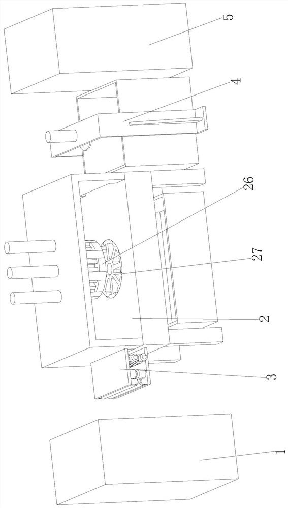
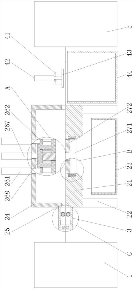
[0033] Refer to 1-8, a servo motor rotor punching manufacturing process, which uses a servo motor rotor punching manufacturing equipment, the servo motor rotor punching manufacturing equipment includes a conveyor 1, a stamping device 2, The limiting device 3, the collecting device 4 and the retracting machine 5, the conveyor 1, the stamping device 2, the collecting device 4 and the retracting machine 5 are arranged in sequence from left to right, and the limiting device 3 is arranged at the left end of the punching device 2 ,in:

[0034] The limiting device 3 incl...


PUM


Abstract

The invention relates to a servo motor rotor punching manufacturing process, which uses a servo motor rotor punching manufacturing and molding equipment, and the servo motor rotor punching manufacturing and molding equipment includes a conveyor, a stamping device, a limiting device, and a collecting device and winder. When using the above-mentioned servo motor rotor punching manufacturing equipment to manufacture and shape the servo motor rotor punching, it includes the following steps: S1, silicon steel sheet conveying; S2, silicon steel sheet limit position; S3, silicon steel sheet stamping; S4, punching Collection; S5, silicon steel sheet coiling. The invention can effectively reduce the deformation amount of the edge of the silicon steel sheet due to the stress in the punching process, increase the flatness of the punched sheet of the rotor iron core, and thus improve the product quality.

Description

technical field [0001] The invention relates to the technical field of motor rotor punching, in particular to a manufacturing process for servo motor rotor punching. Background technique [0002] Servo motor refers to the engine that controls the operation of mechanical components in the servo system, and is an auxiliary motor indirect speed change device. The servo motor can control the speed and the position accuracy is very accurate. It can convert the voltage signal into torque and speed to drive the control object. The servo motor rotor is also a rotating part in the servo motor. It is used to realize electrical energy and mechanical energy, mechanical energy and For the conversion device of electric energy, the rotor iron core is formed by stacking silicon steel punching sheets, which are formed by stamping in production, and a ring-shaped rotor iron core punching sheet is obtained by stamping the silicon steel sheets. [0003] However, the existing servo motor rotor ...

Claims


Application Information

Patent Timeline
Patent Type & Authority Patents(China)
IPC IPC(8): H02K15/02B21D28/02B08B1/02B08B1/20
CPCH02K15/02B21D28/02B08B1/12B08B1/20
Inventor 庞呈
Owner WENLING SHANSHI CHONGJIAN FACTORY
Learn More