Control method and system of power factor correction circuit

A technology of power factor correction and control method, applied in the field of circuits, which can solve the problems of distortion, high system cost, signal delay, etc.

Pending Publication Date: 2021-07-06
VERTIV CORP
View PDF0 Cites 0 Cited by
  • Summary
  • Abstract
  • Description
  • Claims
  • Application Information

AI Technical Summary

Problems solved by technology

[0007] The embodiment of the present invention provides a control method and system of a power factor correction circuit, so as to at least solve the technical ...

Method used


Image

  • Control method and system of power factor correction circuit
  • Control method and system of power factor correction circuit
  • Control method and system of power factor correction circuit

Examples


Embodiment 1

[0038] An embodiment of the present invention provides a control system for a power factor correction circuit.

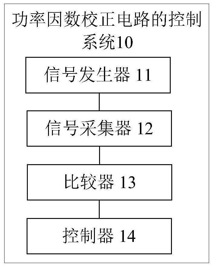
[0039] figure 1 is a schematic diagram of a control system of a power factor correction circuit according to an embodiment of the present invention. Such as figure 1 As shown, the control system 10 of the power factor correction circuit may include: a signal generator 11 , a signal collector 12 , a comparator 13 and a controller 14 .

[0040] The signal generator 11 is located at the control ground and is used for sending out low-frequency analog signals, wherein the low-frequency analog signals change within the power frequency period.

[0041] In this embodiment, the signal generator 11, that is, the signal generating module, can output a periodic low-frequency analog signal. The low-frequency analog signal is a reference signal, which can be a slow-changing analog signal of a power frequency cycle, or can be The calculated inductor current peak value can also ...

Embodiment 2

[0073] According to an embodiment of the present invention, an embodiment of a control method of a power factor correction circuit is provided. It should be noted that the steps shown in the flowcharts of the accompanying drawings can be executed in a computer system such as a set of computer-executable instructions , and, although a logical order is shown in the flowcharts, in some cases the steps shown or described may be performed in an order different from that herein.

[0074] It should be noted that, the control method of the power factor correction circuit in this embodiment can be executed by the control system of the above-mentioned power factor correction circuit of the present invention.

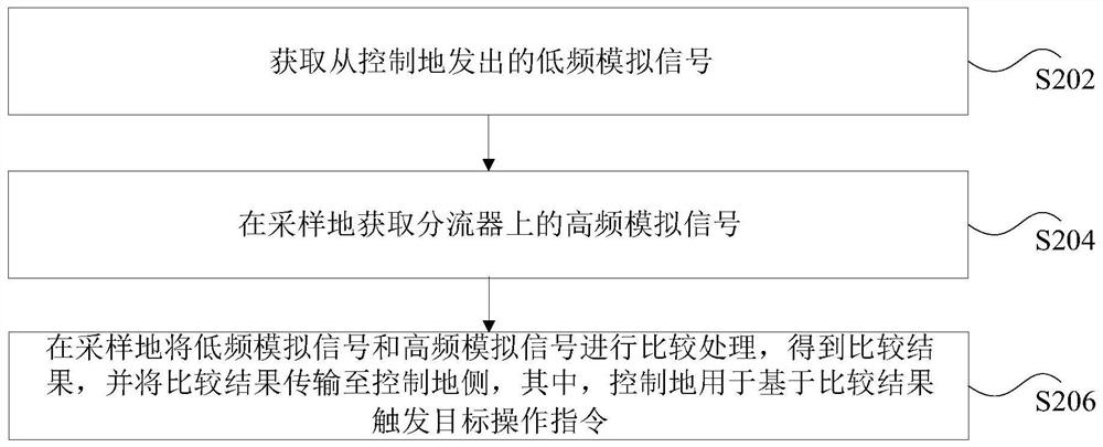
[0075] figure 2 It is a flowchart of a control method of a power factor correction circuit according to an embodiment of the present invention. Such as figure 2 As shown, the method may include the following steps:

[0076] Step S202, acquiring a low-frequency analog signal s...

Embodiment 3

[0105] The technical solution of the present application will be illustrated below in combination with preferred implementation modes.

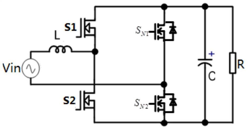
[0106] With the continuous improvement of AC-DC efficiency and power density requirements, there are usually two types of control modes used in totem pole circuits, one is continuous current conduction mode (CCM), the control of this mode is simple, but for Semiconductor power transistors made of silicon materials have relatively low efficiency due to the large reverse recovery loss of their body diodes at the moment of switching commutation. Therefore, this mode usually uses silicon carbide (SiC) with small reverse recovery and low cost requirements. ) or gallium nitride (GaN) material semiconductor power tube; the other type is critical continuous mode (CRM) or triangular wave current mode (TCM), because it can realize part or all of the zero voltage turn-on, and there is no reverse recovery problem, Gradually being more and more applied to...


PUM


Abstract

The invention discloses a control method and system of a power factor correction circuit. The method comprises the steps: acquiring a low-frequency analog signal emitted from a control place, wherein the low-frequency analog signal changes in a power frequency period; obtaining high-frequency analog signals on the diverter at a sampling ground, wherein the potential of the sampling ground is different from that of the control ground; carrying out comparison of the low-frequency analog signal and the high-frequency analog signal at the sampling place to obtain a comparison result, and transmitting the comparison result to the control place, wherein the control place is used for triggering a target operation instruction based on the comparison result. According to the invention, the technical problems of complex control of the power factor correction circuit and high system cost caused by delay and distortion of the high-frequency signal in the isolation transmission process are solved.

Description

technical field [0001] The present invention relates to the field of circuits, in particular to a control method and system for a power factor correction circuit. Background technique [0002] At present, with the continuous improvement of AC-DC efficiency and power density requirements, the application of totem pole circuits is becoming more and more extensive. Relatively complex control strategies in industrial applications are usually implemented using digital platforms (such as digital signal processors DSP). However, digital platforms such as DSP are extremely sensitive to the position of the potential of the system control ground and the quality of the input signal. Usually, they can only accept stable and interference-free ground planes, limited range, clean quality, and no delay input signals. [0003] In the power factor correction circuit, for the circuit whose inductor current sampling scheme is "shunt resistor + amplifier", in order to make the inductor current ...

Claims


Application Information

Patent Timeline
IPC IPC(8): H02M1/42
CPCH02M1/4258Y02B70/10
Inventor 张帆王艳芳首福俊李剑
Owner VERTIV CORP
Why Eureka
Try Eureka