Positioning device

A positioning device and lifting device technology, which is applied in positioning devices, manufacturing tools, metal processing machinery parts, etc., can solve the problems of inaccurate flatness of the instrument grid, uneven force on the instrument grid components, and poor processing accuracy. Achieve the effect of easy machining precision, simple structure and reasonable layout

Pending Publication Date: 2021-07-09
上海第一机床厂有限公司
View PDF0 Cites 0 Cited by
  • Summary
  • Abstract
  • Description
  • Claims
  • Application Information

AI Technical Summary

Problems solved by technology

[0004] The purpose of the present invention is to provide a positioning device to solve the technical problems of inaccurate instrument grid flatness of the instrument grid assembly, resulting in uneven force, poor stability, and poor processing accuracy of the instrument grid assembly

Method used


Image

  • Positioning device
  • Positioning device
  • Positioning device

Examples


Embodiment Construction

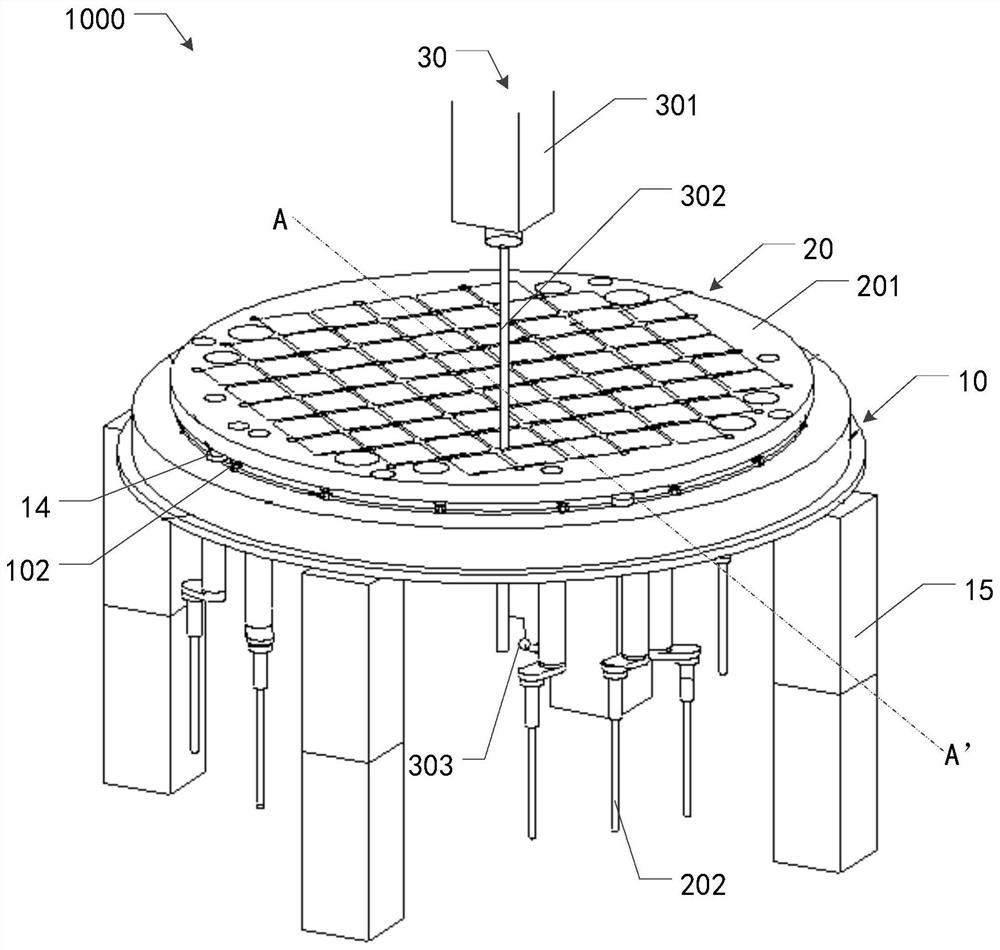
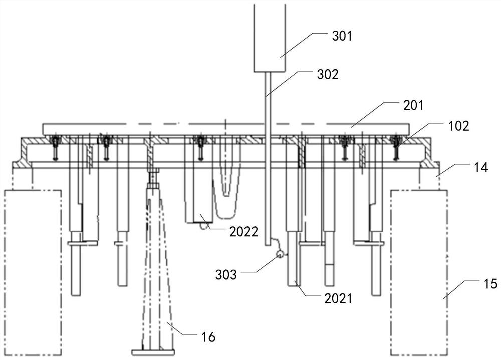
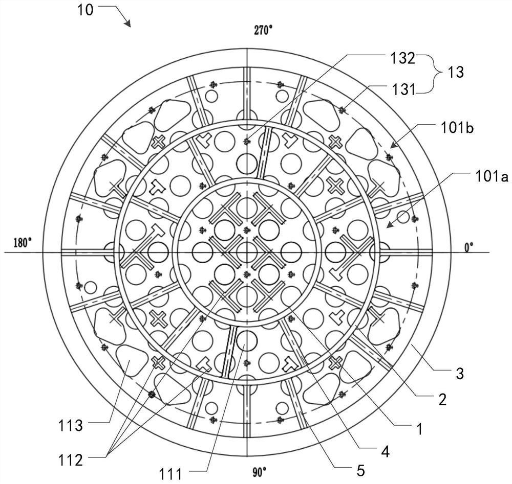
[0047] The technical solutions in the embodiments of the present application will be clearly and completely described below in conjunction with the drawings in the embodiments of the present application. Apparently, the described embodiments are only some of the embodiments of this application, not all of them.

[0048] In the description of the present application, it should be understood that the terms "center", "longitudinal", "transverse", "length", "width", "thickness", "upper", "lower", "front", " The orientation or positional relationship indicated by "rear", "left", "right", "vertical", "horizontal", "top", "bottom", "inner", "outer", etc. is based on the orientation shown in the drawings Or positional relationship is only for the convenience of describing the present application and simplifying the description, but does not indicate or imply that the device or element referred to must have a specific orientation, be constructed and operated in a specific orientation, ...


PUM


Abstract

The invention discloses a positioning device. The positioning device comprises a supporting device used for supporting an instrument grillwork assembly, the supported instrument grillwork assembly comprises an instrument grillwork and an assembly extending downwards from the bottom of the instrument grillwork, and the supporting device is arranged at the bottom of the instrument grillwork and used for supporting the instrument grillwork. The supporting device comprises a supporting body and multiple lifting devices. One end of each lifting device is installed on the supporting body, and the other end of each lifting device is connected to the bottom of the instrument grillwork in a lifting manner so that the levelness of the instrument grillwork can be adjusted. By means of the lifting devices, accurate positioning is provided for installation of the instrument grillwork assembly, the equipment use cost of a machine tool and a cutter is reduced, the machining efficiency is improved, and the manufacturing period is remarkably shortened.

Description

technical field [0001] The present application relates to the technical field of machining, in particular to a positioning device for an instrument grid assembly. Background technique [0002] The measuring instrument grid support assembly (instrument grid assembly, hereinafter referred to as IGA assembly) includes an instrument grid and irregularly distributed components extending along the surface of the instrument grid. The circumferential diameter of the instrument grid is usually between 3000-4000mm, and its thickness is about 100mm. Wherein, after the welding and rectification of components are completed on the bottom surface of the instrument grid, the instrument grid still needs to be machined. However, in the process of machining, since the connecting side of the instrument grid and the components directly contacts the processing platform, it is difficult to meet the flatness requirements of the instrument grid components, and it is difficult to meet the verticalit...

Claims


Application Information

Patent Timeline
Patent Type & Authority Applications(China)
IPC IPC(8): B23Q3/06
CPCB23Q3/06
Inventor 唐剑峰周祖谦秦沈杰辛正高郎朋飞
Owner 上海第一机床厂有限公司
Why Eureka
Try Eureka