
Packaging paperboard cutting and punching device and cutting method thereof

A technology for packaging cardboard and detection device, applied in packaging, transportation and packaging, paper/cardboard containers, etc., can solve the problems of increased production cost, damage, low production efficiency, etc., to save costs, improve friction, and improve efficiency. Effect

Inactive Publication Date: 2021-07-09
毛振高
View PDF0 Cites 2 Cited by
  • Summary
  • Abstract
  • Description
  • Claims
  • Application Information

AI Technical Summary

Problems solved by technology

[0002] The existing wrapping paper cutting step is usually to cut the wrapping paper into a suitable rectangular sheet, and then use a cutting device to cut the rectangular sheet into various packaging shapes (for example: the shape of a shoe box). This cutting method not only The packaging cardboard needs to be cut into rectangular pieces of paper first, and manual feeding is required. Therefore, the production efficiency is low. At the same time, due to the defect of poor precision in manual feeding, in order to ensure the cutting yield, the general practice is to Leave enough margin on the edge of the paper sheet (that is, the area of ​​the rectangular paper sheet will be larger than the effective die area) for subsequent trimming, thus increasing the production cost;
[0003] Not only that, in order to improve the air-dispersing effect of the current packaging box, holes are usually punched on the packaging box, but the existing step is generally carried out after the packaging box is formed, and after the packaging box is formed, in order to avoid damage to the packaging box, This process is generally done manually, therefore, there is a disadvantage of low efficiency

Method used


Image

  • Packaging paperboard cutting and punching device and cutting method thereof
  • Packaging paperboard cutting and punching device and cutting method thereof
  • Packaging paperboard cutting and punching device and cutting method thereof

Examples


Embodiment 1

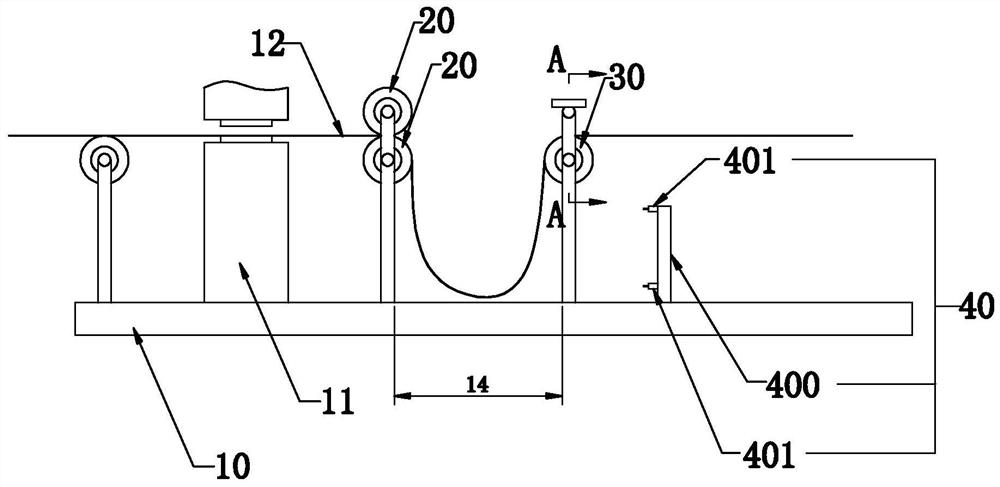
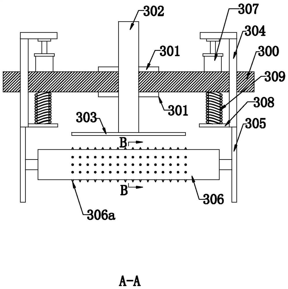
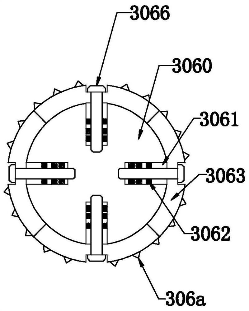
[0047] Such as Figure 1-4 As shown, the present invention discloses a packaging cardboard cutting and opening device, which includes a machine body 10 and a cutting part 11 arranged on the machine body 10. In a specific embodiment of the invention, at least one And it is used to convey the packing cardboard 12 and is controlled by the fixed speed roller 20 of the first plc motor, at least one is used for conveying the packaging cardboard 12 and is controlled by the second plc motor speed regulating punching assembly 30 and is used to control the first plc motor And the control unit of the second plc motor; wherein, between the fixed speed roller 20 and the speed regulating perforation assembly 30, a stacking area 14 for packing cardboard 12 is formed, and the body 10 is provided with a fixed speed roller 20 and a The detection device 40 between the speed-regulating punching assembly 30, the detection device 40 is used to detect the stacking depth of the packaging cardboard 12...

Embodiment 2

[0063] Embodiment 2, the difference with embodiment 1 is that

[0064] Such as Figure 5-Figure 9 As shown, in the specific embodiment of the present invention, it includes a supporting module 5 arranged in the stacking area 14 and used to support the packaging cardboard 12. The supporting module 5 includes a frame 50 arranged on the machine body 10, a rotating The first support bar 51 and the second support bar 52 that are connected to the frame 50 and arranged at intervals, and the support platform 54 that is connected with the first support bar 51 and the second support bar 52 and is used to support the packaging cardboard 12 And the first cylinder 55 hinged on the frame 50 and used to control the movement of the first support rod 51 around the hinge point; wherein, the first support rod 51 includes a first rod body 510, and the first secondary rod 511 fixedly connected to the rod body 510; The second sub-rod 521 on the top, a coupling 53 is provided between the first sub...

Embodiment 3

[0075] Embodiment 3, the difference with embodiment 2 is that

[0076] Such as Figure 10-Figure 13As shown, in the specific embodiment of the present invention, it also includes an auxiliary device 6 arranged on the support table 54 and used to supply air to the packaging cardboard 12 and assist the lifting of the packaging cardboard 12. The auxiliary device 6 includes a row of spacers The first air outlet hole 61 distributed on the support platform 54 and located in the center, at least two rows of second air outlet holes 62 arranged at intervals on both sides of the first air outlet hole 61, are arranged on the support platform 54 and used for An air distribution device 65 for supplying air to the first air outlet 61 and the second air outlet 62, and an air pump 63 installed at the bottom of the support table 54 and used to supply air to the input end of the air distribution device 64; wherein the air distribution The device 65 includes a distributing body 651 arranged on ...


PUM


Abstract

The invention relates to a packaging paperboard cutting and punching device and a cutting method thereof. The packaging paperboard cutting and punching device comprises a machine body and a cutting part arranged on the machine body; the packaging paperboard cutting and punching device is characterized by comprising at least one constant-speed roller which is arranged on any side of the cutting part, used for conveying a packaging paperboard and controlled by a first plc motor, at least one speed-regulating punching assembly which is used for conveying the packaging paperboard and controlled by a second plc motor, and a control unit which is used for controlling the first plc motor and the second plc motor, wherein an accumulation area for accumulation of the packaging paperboards is formed between the constant-speed roller and the speed-regulating punching assembly; a detection device located between the constant-speed roller and the speed-regulating punching assembly is arranged on the machine body, and the detection device is used for detecting the accumulation depth of the packaging paperboards in the accumulation area and feeding the accumulation depth back to the control unit; and the control unit controls the second plc motor to drive the speed-regulating punching assembly to rotate on the basis of a detection result of the detection device. The packaging paperboard cutting and punching device has the beneficial effects that the efficiency is high, and the packaging paperboard can be punched before being cut.

Description

technical field [0001] The invention relates to the technical field of packaging paper cutting, in particular to a packaging cardboard cutting and opening device and a cutting method thereof. Background technique [0002] The existing wrapping paper cutting step is usually to cut the wrapping paper into a suitable rectangular sheet, and then use a cutting device to cut the rectangular sheet into various packaging shapes (for example: the shape of a shoe box). This cutting method not only The packaging cardboard needs to be cut into rectangular pieces of paper first, and manual feeding is required. Therefore, the production efficiency is low. At the same time, due to the defect of poor precision in manual feeding, in order to ensure the cutting yield, the general practice is to Leave enough margin on the edge of the paper sheet (that is, the area of ​​the rectangular paper sheet will be larger than the effective die area) for subsequent trimming, thus increasing the productio...

Claims


Application Information

Patent Timeline
Patent Type & Authority Applications(China)
IPC IPC(8): B31B50/10B31B50/00B31B50/02B31B50/14B31B50/16
CPCB31B50/006B31B50/022B31B50/102B31B50/146B31B50/16
Inventor 不公告发明人
Owner 毛振高
Learn More