
Hydraulic mechanical heat dissipation device for railway transportation

A technology of hydraulic machinery and heat dissipation device, which is applied in the direction of fluid pressure actuating device, mechanical equipment, oil supply tank device, etc., can solve the problems of affecting heat discharge, cylinder explosion, reduction of heat dissipation effect of hydraulic oil radiator, etc., and achieves convenient collection. Effect

Inactive Publication Date: 2021-07-09
安亚雷
View PDF1 Cites 0 Cited by
  • Summary
  • Abstract
  • Description
  • Claims
  • Application Information

AI Technical Summary

Problems solved by technology

The hydraulic mechanical heat dissipation device in the above patent has the following disadvantages: there is a protective cover on the outside of the fan, and dust is easy to accumulate on the surface of the protective cover to form a gray net, which seriously affects the heat discharge and reduces the cooling effect of the hydraulic oil radiator. The phenomenon of excessive temperature damage or even cylinder explosion occurs

Method used


Image

  • Hydraulic mechanical heat dissipation device for railway transportation
  • Hydraulic mechanical heat dissipation device for railway transportation
  • Hydraulic mechanical heat dissipation device for railway transportation

Examples


Embodiment 1

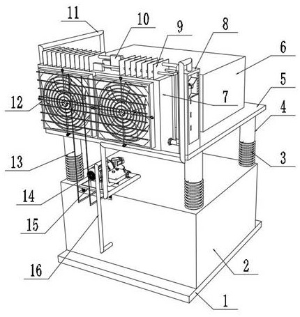
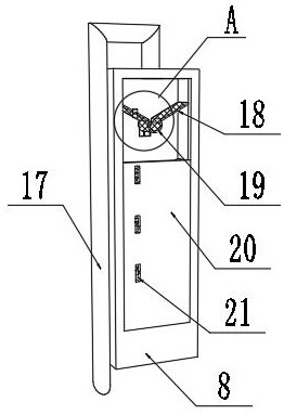
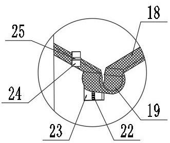
[0034] Hydraulic mechanical heat dissipation device for railway transportation, such as Figure 1-6As shown, including the first fuel tank 2 and the second tank 6 fixed to the top of the base 1, the bottom end of the second oil tank 6 is fixed to the top end of the first fuel tank 2 by a damper buffer mechanism; the damping buffer mechanism includes four groups The telescopic column 4 and the first spring 3 wrapped in the outer wall of the telescopic column 4, the bottom end of the second oil tank 6 secures the support plate 5 by the bolt, and both ends of the telescopic column 4 are fixed to the bottom corner of the support plate 5, respectively, respectively. The top angle of the tank 2, the outer side of the telescopic column 4, the first spring 3 can effectively support the second oil tank 6 above the support plate 5 while reducing the vibration wear of the device during rail transportation; the top end of the support plate 5 One side is fixed by screws, and the fan side of the...

Embodiment 2

[0039] Hydraulic mechanical heat dissipation device for railway transportation, such as Figure 7 As shown, in order to further improve the problem of clearing the dust-proof mesh 12 surface product; the present embodiment, the following improvements are made based on the first embodiment: the outer wall of the cleaner 27 is provided with a bevel 30, a bevel 30, and a cleaning frame. 27 Near the outer wall of the hydraulic oil heat exchanger 7 is provided with two or more cleaning brushes 29; by providing a bevel 30, the design of the slope 30 can prevent the straight-sheet cleaning frame 27 to block dust falling, providing a sweep dust Cleaning space, avoiding the phenomenon of cleaning of the cleaning operation, and two outer walls of the bevel 30 and the cleaner 27 are provided with two or more outer cleaning brushes 29, and the vibration generated by the oil pump 14 can be used. The vibrating cleaning 29 performs scratching dust, improves the cleaning effect.

[0040] When used...


PUM


Abstract

The invention discloses a hydraulic mechanical heat dissipation device for railway transportation, relates to the technical field of railway transportation, and solves the problem that dust is easily accumulated on the surface layer of a protective cover to form a dust net. The device specifically comprises a first oil tank and a second oil tank which are fixed to the top of a base, wherein the bottom end of the second oil tank is fixed to the top end of the first oil tank through a damping buffering mechanism; and the damping and buffering mechanism comprises four sets of telescopic legs and first springs wrapping the outer walls of the telescopic legs, and a supporting plate is fixed to the bottom end of the second oil tank through bolts. A cleaning rack is arranged, in order to reduce the wind influence of the cleaning rack on a hydraulic oil radiator, ten or more sets of exhaust holes are formed in the side wall of the cleaning rack, in order to reduce the accumulation of dust in the exhaust holes, the exhaust holes are of circular truncated cone hole structures, the small-aperture positions of the exhaust holes face inwards, hot air is exhausted through the exhaust holes after the dust is cleaned, and meanwhile, due to the inclined design, dust can be prevented from being accumulated in the holes.

Description

Technical field [0001] The present invention relates to the field of railway transportation techniques, and more particularly to a hydraulic mechanical heat dissipation apparatus for railway transportation. Background technique [0002] In the fields of mechanical, chemical, construction, etc., the use of hydraulic structures can be used as the power of equipment, and there is a movement in multiple fields, and there is a lack of hydraulic structures will make most of their daily lives. It is impossible to use, so the improvement of hydraulic structures is very necessary. The process of hydraulic devices produces a lot of heat, which can affect the use of hydraulic machines when they cannot disappear. [0003] According to the search, the Chinese patent application No. 201811460723.4 discloses a hydraulic mechanical heat dissipation device, including hydraulic machinery, a display, a semiconductor refrigerator, a protective cover, a support post, a fan, and a temperature meter, c...

Claims


Application Information

Patent Timeline
Patent Type & Authority Applications(China)
IPC IPC(8): F15B1/26F15B21/00F15B21/041F15B21/0423B08B1/00B08B15/04
CPCF15B21/00F15B1/26F15B21/0423F15B21/041B08B15/04B08B1/12
Inventor 安亚雷
Owner 安亚雷
Learn More