
Ultrasonic phased array detection device and detection method

An ultrasonic phased array and detection method technology, applied in the direction of measuring devices, using ultrasonic/sonic/infrasonic waves, using sound waves/ultrasonic/infrasonic waves to analyze solids, etc., can solve the problem of inaccurate defect identification and processing in flaw detection results, measurement speed, The accuracy cannot meet the requirements, the automatic detection software is not perfect, etc., so as to avoid the easy missed detection of weld detection, improve the detection accuracy and reliability, and extend the working range

Pending Publication Date: 2021-07-09
SICHUAN UNIV
View PDF8 Cites 1 Cited by
  • Summary
  • Abstract
  • Description
  • Claims
  • Application Information

AI Technical Summary

Problems solved by technology

But the analysis of defect signals in complex ultrasound data after inspection has so far relied heavily on experienced inspectors
Commonly used automated systems that use simple decisions (such as signal amplitude thresholds) can no longer meet the needs of identifying and classifying defects. The deep learning network that has made breakthroughs since 2012 has brought new exploration directions to the automatic identification of weld defects.
[0005] Domestic ultrasonic phased array detection technology is relatively lagging behind in related research and application, and the automatic detection software and automatic detection equipment are not perfect enough, resulting in the measurement speed and accuracy in engineering applications not meeting the requirements. In addition, the internal and external structures of the measured workpiece Complicated, making the identification and processing of defects in the flaw detection results inaccurate

Method used


Image

  • Ultrasonic phased array detection device and detection method
  • Ultrasonic phased array detection device and detection method
  • Ultrasonic phased array detection device and detection method

Examples


Embodiment Construction

[0051] The following will clearly and completely describe the technical solutions in the embodiments of the present invention with reference to the accompanying drawings in the embodiments of the present invention. Obviously, the described embodiments are only some, not all, embodiments of the present invention. Based on the embodiments of the present invention, all other embodiments obtained by persons of ordinary skill in the art without making creative efforts belong to the protection scope of the present invention.

[0052] In order to make the above objects, features and advantages of the present invention more comprehensible, the present invention will be further described in detail below in conjunction with the accompanying drawings and specific embodiments.

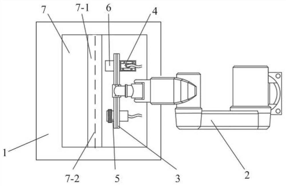
[0053] figure 1 It is a structural schematic diagram of the ultrasonic phased array detection device of the present invention. Such as figure 1 As shown, the ultrasonic phased array detection device of the prese...


PUM


Abstract

The invention relates to an ultrasonic phased array detection device and a detection method. A detection platform of the detection device is arranged on a platform moving guide rail, and the detection platform is used for transmitting a to-be-detected workpiece; the fixed end of the clamping mechanism is fixed on the moving device, and the clamping end of the clamping mechanism is used for clamping the phased array probe and the visual sensor; the position encoder is integrated on the wedge block, and the wedge block and the phased array probe are fixed into a whole; the output ends of the visual sensor, the position encoder and the phased array probe are all connected with the controller, and the output end of the controller is connected with a driving motor of the moving device; the controller is used for adjusting the moving parameters of the moving device according to the parameters of the workpiece to be detected, the images collected by the visual sensor and the position data collected by the position encoder, and obtaining the detection result of the workpiece to be detected according to the detection data of the phased array probe. According to the invention, the defect detection precision can be improved.

Description

technical field [0001] The invention relates to the field of ultrasonic detection, in particular to an ultrasonic phased array detection device and a detection method. Background technique [0002] Traditional nondestructive testing methods for weld defects include radiographic testing, ultrasonic testing, magnetic particle testing, and penetrant testing. The above-mentioned methods often have limitations such as large blind spots, low precision, long time consumption and great harm when detecting weld seams. When conventional ultrasound detects welds with complex external structures and internal defects, the movement of the probe is limited by the space, which is likely to cause missed inspections. Moreover, the imaging of flaw detection results is not intuitive, and it is not easy to identify and analyze defects. [0003] As an important branch of ultrasonic testing, ultrasonic phased array testing jumped from the medical field to the industrial field in the early 1980s....

Claims


Application Information

Patent Timeline
Patent Type & Authority Applications(China)
IPC IPC(8): G01N29/07G01N29/24G01N29/265G01B17/06
CPCG01N29/07G01N29/2456G01N29/265G01B17/06G01N2291/105G01N2291/267
Inventor 赵秀粉谢正旺殷国富许世法
Owner SICHUAN UNIV
Learn More