
Trigger circuit of RBDT device, and application thereof in pulse generator

A trigger circuit and device technology, which is applied to electric pulse generator circuits, electrical components, output power conversion devices, etc., can solve the problems of limited trigger voltage rise rate, large trigger circuit volume, and complicated control, and achieve simplified control, The effect of compact size and optimized working characteristics

Active Publication Date: 2021-07-09
HUAZHONG UNIV OF SCI & TECH
View PDF7 Cites 0 Cited by
  • Summary
  • Abstract
  • Description
  • Claims
  • Application Information

AI Technical Summary

Problems solved by technology

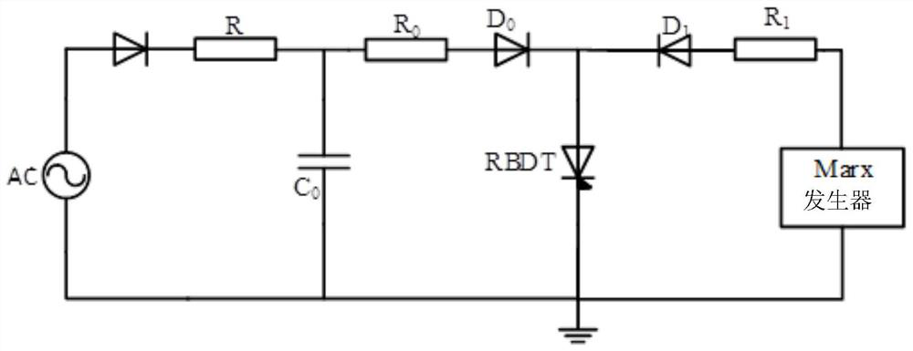
[0008] Aiming at the defects of the prior art, the object of the present invention is to provide a trigger circuit of an RBDT device and its application in a pulse generator, aiming at solving the problem of excessive volume of the trigger circuit, complicated control and poor reliability in the application of the RBDT device. , and the problem that the rate of rise of the trigger voltage of the output is limited

Method used


Image

  • Trigger circuit of RBDT device, and application thereof in pulse generator
  • Trigger circuit of RBDT device, and application thereof in pulse generator
  • Trigger circuit of RBDT device, and application thereof in pulse generator

Examples


Embodiment Construction

[0042] In order to make the object, technical solution and advantages of the present invention clearer, the present invention will be further described in detail below in conjunction with the accompanying drawings and embodiments. It should be understood that the specific embodiments described here are only used to explain the present invention, not to limit the present invention.

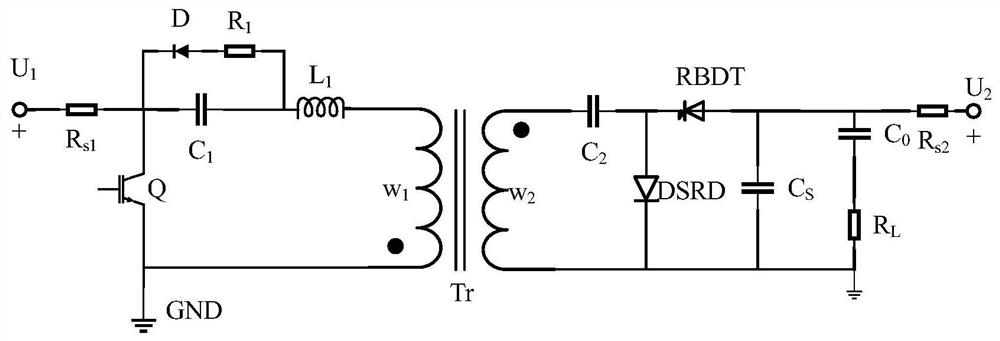
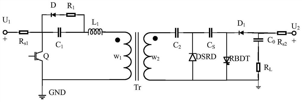
[0043] Aiming at the above defects or improvement needs of the prior art, the present invention provides a trigger circuit topology of RBDT devices. The present invention uses a pulse power circuit based on DSRD devices as the trigger circuit of RBDT devices, which can reduce the volume of the pulse generator and increase the pulse output. Generator reliability, optimize the working characteristics of RBDT devices.

[0044] Therefore, in order to make the pulse generator based on the RBDT device more compact, improve the reliability of the pulse generator, and provide a higher trigger voltage rise ...


PUM


Abstract

The invention provides a trigger circuit of an RBDT device, and an application thereof in a pulse generator. A pulse power circuit based on the DSRD device is used as the trigger circuit of the RBDT device, due to the particularity of the working principle of the DSRD device, multiple DSRD devices can be directly connected in series to be used, and the requirement for triggering synchronism of multiple full-control switching tubes does not exist, so the reliability of the trigger circuit of the RBDT device is improved. In addition, compared with an existing Marx generator, the trigger circuit based on the DSRD device is more compact in size, the number of needed full-control switch tubes is smaller, the size of the pulse generator can be reduced, control over the pulse generator is simplified, the rise rate of output voltage of the trigger circuit based on the DSRD device is higher, the working characteristics of the RBDT device can be optimized, and the efficiency of the pulse generator is improved. A trigger circuit topology of the DSRD device containing a saturable transformer is adopted, so the requirement for the voltage withstand level of a primary side switching tube Q can be lowered, and the cost of the pulse generator is saved.

Description

technical field [0001] The invention belongs to the field of pulse power circuits, and more specifically relates to a trigger circuit of an RBDT device and its application in a pulse generator. Background technique [0002] Pulse power technology is an emerging technology field that studies the storage of energy for a relatively long period of time, then undergoes rapid compression, conversion, and finally effectively releases to the load. Pulse power technology plays a very important role in scientific research and military applications. Its military applications are reflected in: nuclear explosion radiation effect simulation, inertial confinement nuclear fusion, high-power microwave drive source, electromagnetic emission and high-power laser. In addition, with the continuous development of pulse power technology, pulse power technology has gradually been applied to civil and industrial fields such as waste gas and wastewater treatment, material preparation, disinfection an...

Claims


Application Information

Patent Timeline
Patent Type & Authority Applications(China)
IPC IPC(8): H02M9/04H02M3/28H03K3/02
CPCH02M11/00H02M3/28H03K3/02
Inventor 梁琳黄鑫远
Owner HUAZHONG UNIV OF SCI & TECH
Learn More