
High-linearity phase interpolation circuit

A phase interpolation and high linearity technology, applied in the direction of single output arrangement, etc., can solve the problem of sacrificing chip area and power consumption, achieve the effect of sacrificing area and power consumption, benefiting layout realization, and avoiding the difficulty of realization

Active Publication Date: 2021-07-09
WUXI ESIONTECH CO LTD +1
View PDF5 Cites 1 Cited by
  • Summary
  • Abstract
  • Description
  • Claims
  • Application Information

AI Technical Summary

Problems solved by technology

In order to improve the adjustment accuracy, the current common practice is to increase the length N of phase interpolation to compensate for the lack of linearity, but this method will sacrifice chip area and power consumption

Method used


Image

  • High-linearity phase interpolation circuit
  • High-linearity phase interpolation circuit
  • High-linearity phase interpolation circuit

Examples


Embodiment Construction

[0032] The specific embodiments of the present invention will be further described below in conjunction with the accompanying drawings.

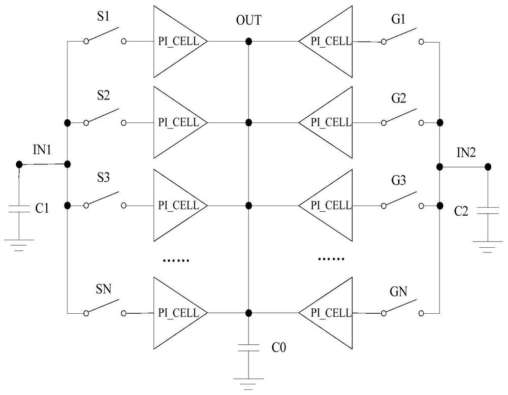
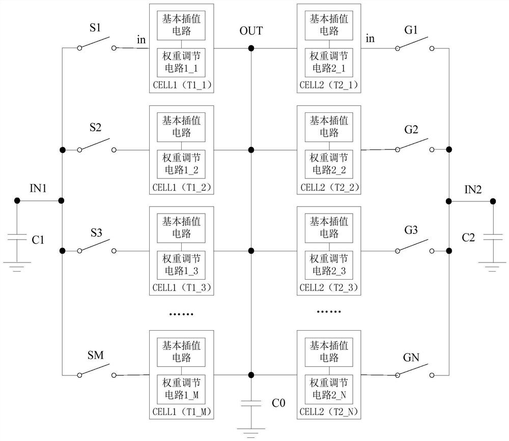
[0033]The present application discloses a phase interpolation circuit with high linearity. The phase interpolation circuit includes a first parallel circuit composed of M phase interpolation units and a second parallel circuit composed of N phase interpolation units. The input of each phase interpolation unit The terminal in is connected to the input terminal of the parallel circuit, and the output terminal is connected to the output terminal of the parallel circuit. Such as figure 1 As shown, the input terminal of the first parallel circuit is connected to the first clock input terminal IN1 and grounded through the first capacitor C1, and the output terminal of the first parallel circuit is connected to the clock output terminal OUT. The input terminal of the second parallel circuit is connected to the second clock input terminal IN2 and g...


PUM


Abstract

The invention discloses a high-linearity phase interpolation circuit, which relates to the field of phase interpolation circuits. Each phase interpolation unit in the phase interpolation circuit corresponds to a respective target output weight; the target output weight of each phase interpolation unit is determined through iteration, so that the phase difference degree among all output clock signals of the phase interpolation circuit is minimum; according to the phase interpolation circuit, nonlinearity is artificially added through circuit parameters of all the phase interpolation units to compensate nonlinearity existing in the MOS tube, the linearity of the phase interpolation circuit can be effectively improved, the implementation mode is simple, the implementation difficulty of a complex compensation technology is avoided, the phase interpolation length does not need to be increased, and the area and power consumption are not sacrificed.

Description

technical field [0001] The invention relates to the field of phase interpolation circuits, in particular to a phase interpolation circuit with high linearity. Background technique [0002] In the high-speed interface chip, when the data is input, a clock located in the center of the data is required to sample it for subsequent data processing. With different working conditions, the location of the data center is also changing, which requires that the phase of the sampling clock can have a corresponding adjustment range, or the clock needs to achieve fine phase adjustment, so as to obtain more timing margin for the system ( timing margin). [0003] Phase interpolation (PI, Phase Interpolation) is a common technique for fine phase adjustment. When applied to parallel interfaces such as DDR, it often cooperates with DLL to perform phase interpolation on adjacent phase clocks generated by DLL to obtain more refined multi-phase clock output. When applied to a serial interface,...

Claims


Application Information

Patent Timeline
Patent Type & Authority Applications(China)
IPC IPC(8): H03K5/13
CPCH03K5/13
Inventor 马锡昆谢宜政
Owner WUXI ESIONTECH CO LTD
Learn More